Product Description
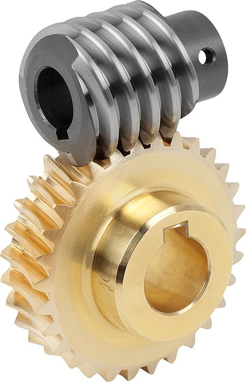
Machining Accuracy Grade 6 Standard Toroidal Worm Gearing Gear
Product Description
CHINAMFG provides one-stop solution service for your metallurgical equipment spare parts, currently we produce rolling mill rolls, guide, blades, gears, sprocket wheels, worm, worm gears, flange processing parts, welding processing parts and etc. Gear rack is a rotating machine part with cut teeth, or cogs, which mesh with another toothed part in order to transmit torque. It includes spur gear, helical gear, skew gear, bevel gear, spiral bevel gear and so on. It is widely used for all kinds of machinery equipment.
| Product Name | Gear Racks |
| Material | C45, 40Cr, 20CrMnTi, 42CrMo, Copper, Stainless steel |
| Tolerance | 0.001mm – 0.01mm – 0.1mm |
| Tooth Hardness | 50-60 HRC |
| Length | Customized |
| Processing | Forging, Machining, Hobbing, Milling, Shaving, Grinding, Heat treatment |
| Inspection | Material Report, Dimensions Checking Report, Hardness Report |
| Payment | L/C, Western Union, D/P, D/A, T/T, MoneyGram |
| Lead Time | 4 weeks |
Company Profile
HangZhou CHINAMFG Heavy Industry Technology Development Co., Ltd. is a leading enterprise in the wear-resistant casting of large engineering machinery and the forging of large equipment parts located in the New Material Industrial Park, Xihu (West Lake) Dis. High-Tech Zone, HangZhou City, the company covers an area of 90 Square kilometer and currently has more than 300 employees. The company is equipped with lost molding production line and lost casting production line imported from FATA Company in Italy, Inductotherm Vacuum Degassing Furnace(USA), Foseco Casting Technology(U.K), SPECTRO Spectrometer (Germany), the currently most advanced ZZ418A vertical parting flaskless shoot squeeze molding machine Disa production line, horizontal molding line and self-control lost casting production line in China, the most advanced sand treatment system in China. With 3 gas trolley heat treatment CHINAMFG and pusher-type CHINAMFG full-automatic heat treatment production lines, the company can annually produce 30,000 tons of various wear-resisting castings and metallurgical equipment forging parts.
Manufacturing Technique
Packing and Shipping
To better ensure the safety of your goods, professional, environmentally friendly, convenient and efficient packaging services will be provided. After goods well packaged, we need only 1 day ship goods to ZheJiang port, which means that most of the spare parts you bought from Hyton, it will get your port within 45 days all around the world if shipment by sea.
Our Advantages
1)Your inquiry related to our product & price will be rapidly.
2) Well trained & experienced staff are to answer all your inquiries in English of course.
3) Your business relationship with us will be confidential to any third party.
4) One stop purchase service: extensive rang of products for qualified offering.
5) We response to client’s inquiry within 12 hours.
FAQ
1.Q: What kind of products do you make?
A: We specialize in metallurgical equipment casting and forging parts, such as forging rolls, guide, blades, gears, sprocket wheels, worm, worm gears, flange processing parts, welding processing parts and etc.
2.Q: What kind of material do you offer?
A: High manganese steel, high chrome iron, alloy steel, low carbon steel, medium carbon steel, Stainless Steel and etc.
3.Q: What is your time of delivery?
A: Our lead time is generally 2-4 weeks for casting parts and shipping time is about 2-4 weeks.
4.Q: How to test your quality?
A: We will show you material inspection and measurement inspection after fininsh the goods, at the same time, we will give you the life time guarantee letter after shipping the goods. The best suggestion to all the customer who may interest our product-Test 2 set first, all the good business relationship all from test and trust.
/* January 22, 2571 19:08:37 */!function(){function s(e,r){var a,o={};try{e&&e.split(“,”).forEach(function(e,t){e&&(a=e.match(/(.*?):(.*)$/))&&1
| Application: | Machinery |
|---|---|
| Hardness: | Hardened Tooth Surface |
| Gear Position: | External Gear |
| Manufacturing Method: | Cut Gear |
| Toothed Portion Shape: | Spur Gear |
| Material: | Stainless Steel |
| Customization: |
Available
| Customized Request |
|---|
What is the lifespan of a typical worm gear?
The lifespan of a typical worm gear can vary depending on several factors, including the quality of materials, design, operating conditions, maintenance practices, and the specific application. Here’s a detailed explanation of the factors that influence the lifespan of a worm gear:
1. Quality of materials: The choice of materials used in the construction of the worm gear greatly impacts its lifespan. High-quality materials, such as hardened steel or bronze, offer better durability, wear resistance, and overall longevity compared to lower-quality materials. The selection of appropriate materials based on the application requirements is crucial for achieving a longer lifespan.
2. Design considerations: The design of the worm gear, including factors such as tooth profile, size, and load distribution, can influence its lifespan. Well-designed worm gears with optimized tooth geometry and proper load-carrying capacity tend to have longer lifespans. Additionally, features like lubrication systems and anti-backlash mechanisms can also contribute to improved durability and extended lifespan.
3. Operating conditions: The operating conditions under which the worm gear operates play a significant role in determining its lifespan. Factors such as load magnitude, speed, temperature, and environmental conditions can affect the wear and fatigue characteristics of the gear. Properly matching the worm gear to the application requirements and ensuring that it operates within specified limits can help prolong its lifespan.
4. Maintenance practices: Regular maintenance and proper lubrication are essential for maximizing the lifespan of a worm gear. Adequate lubrication helps reduce friction, wear, and heat generation, thereby extending the gear’s life. Regular inspections, lubricant replenishment, and timely replacement of worn or damaged components are important maintenance practices that can positively impact the lifespan of the worm gear.
5. Application-specific factors: The specific application in which the worm gear is used can also influence its lifespan. Factors such as operating cycles, torque levels, shock loads, and duty cycles vary between applications and can impact the wear and fatigue experienced by the gear. Understanding the unique requirements and demands of the application and selecting a worm gear that is appropriately rated and designed for those conditions can contribute to a longer lifespan.
Given the variations in materials, designs, operating conditions, and maintenance practices, it is challenging to provide a specific lifespan for a typical worm gear. However, with proper selection, installation, and maintenance, worm gears can have a lifespan ranging from several years to decades, depending on the factors mentioned above.
It is worth noting that monitoring the performance of the worm gear through regular inspections and addressing any signs of wear, damage, or excessive backlash can help identify potential issues early and extend the gear’s lifespan. Additionally, following the manufacturer’s guidelines and recommendations regarding maintenance intervals, lubrication types, and operating limits can significantly contribute to maximizing the lifespan of a worm gear.

What are the potential challenges in designing and manufacturing worm gears?
Designing and manufacturing worm gears can present several challenges due to their unique characteristics and operating conditions. Here’s a detailed explanation of the potential challenges involved:
- Complex geometry: Worm gears have complex geometry with helical threads on the worm shaft and corresponding teeth on the worm wheel. Designing the precise geometry of the gear teeth, including the helix angle, lead angle, and tooth profile, requires careful analysis and calculation to ensure proper meshing and efficient power transmission.
- Gear materials and heat treatment: Selecting suitable materials for worm gears is critical to ensure strength, wear resistance, and durability. The materials must have good friction and wear properties, as well as the ability to withstand the sliding and rolling contact between the worm and the worm wheel. Additionally, heat treatment processes such as carburizing or induction hardening may be necessary to enhance the gear’s surface hardness and improve its load-carrying capacity.
- Lubrication and cooling: Worm gears operate under high contact pressures and sliding velocities, resulting in significant heat generation and lubrication challenges. Proper lubrication is crucial to reduce friction, wear, and heat buildup. Ensuring effective lubricant distribution to all contact surfaces, managing lubricant temperature, and providing adequate cooling mechanisms are important considerations in worm gear design and manufacturing.
- Backlash control: Controlling backlash, which is the clearance between the worm and the worm wheel, is crucial for precise motion control and positional accuracy. Designing the gear teeth and adjusting the clearances to minimize backlash while maintaining proper tooth engagement is a challenge that requires careful consideration of factors such as gear geometry, tolerances, and manufacturing processes.
- Manufacturing accuracy: Achieving the required manufacturing accuracy in worm gears can be challenging due to their complex geometry and tight tolerances. The accurate machining of gear teeth, maintaining proper tooth profiles, and achieving the desired surface finish require advanced machining techniques, specialized tools, and skilled operators.
- Noise and vibration: Worm gears can generate noise and vibration due to the sliding contact between the gear teeth. Designing the gear geometry, tooth profiles, and surface finishes to minimize noise and vibration is a challenge. Additionally, the selection of appropriate materials, lubrication methods, and gear housing design can help reduce noise and vibration levels.
- Efficiency and power loss: Worm gears inherently have lower efficiency compared to other types of gear systems due to the sliding contact and high gear ratios. Minimizing power loss and improving efficiency through optimized gear design, material selection, lubrication, and manufacturing accuracy is a challenge that requires careful balancing of various factors.
- Wear and fatigue: Worm gears are subjected to high contact stresses and cyclic loading, which can lead to wear, pitting, and fatigue failure. Designing the gear teeth for proper load distribution, selecting appropriate materials, and applying suitable surface treatments or coatings are essential to mitigate wear and fatigue issues.
- Cost considerations: Designing and manufacturing worm gears can be cost-intensive due to the complexity of the gear geometry, material requirements, and precision manufacturing processes. Balancing performance requirements with cost considerations is a challenge that requires careful evaluation of the gear’s intended application, performance expectations, and budget constraints.
Addressing these challenges requires a comprehensive understanding of gear design principles, manufacturing processes, material science, and lubrication technologies. Collaboration between design engineers, manufacturing experts, and material specialists is often necessary to overcome these challenges and ensure the successful design and production of high-quality worm gears.

How do you calculate the gear ratio of a worm gear?
Calculating the gear ratio of a worm gear involves determining the number of teeth on the worm wheel and the pitch diameter of both the worm and worm wheel. Here’s the step-by-step process:
- Determine the number of teeth on the worm wheel (Zworm wheel). This information can usually be obtained from the gear specifications or by physically counting the teeth.
- Measure or determine the pitch diameter of the worm (Dworm) and the worm wheel (Dworm wheel). The pitch diameter is the diameter of the reference circle that corresponds to the pitch of the gear. It can be measured directly or calculated using the formula: Dpitch = (Z / P), where Z is the number of teeth and P is the circular pitch (the distance between corresponding points on adjacent teeth).
- Calculate the gear ratio (GR) using the following formula: GR = (Zworm wheel / Zworm) * (Dworm wheel / Dworm).
The gear ratio represents the speed reduction and torque multiplication provided by the worm gear system. A higher gear ratio indicates a greater reduction in speed and higher torque output, while a lower gear ratio results in less speed reduction and lower torque output.
It’s worth noting that in worm gear systems, the gear ratio is also influenced by the helix angle and lead angle of the worm. These angles determine the rate of rotation and axial movement per revolution of the worm. Therefore, when selecting a worm gear, it’s important to consider not only the gear ratio but also the specific design parameters and performance characteristics of the worm and worm wheel.


editor by CX 2024-03-26
China wholesaler Transmission Precision Custom Toothed Spiral Cylindrical Metal Helical Cog-Wheel Spur Gear gear cycle
Product Description
Product Description
Transmission Precision Custom Toothed Spiral cylindrical metal Helical Cog-Wheel Spur Gear
| Item | Customized machined machining gears | |
| Process | CNC machining,CNC milling, cnc lathe machining | |
| material | steel, stainless steel, carbon steel,brass,C360 brass copper, aluminum 7075,7068 brass,C360 brass copper, aluminum Nylon, PA66, NYLON , ABS, PP,PC,PE,POM,PVC,PU,TPR,TPE,TPU,PA,PET,HDPE,PMMA etc | |
| Quality Control | ISO9001 and ISO14001 | |
| Dimension bore tolerances | -/+0.01mm | |
| Quality standard | AGMA, JIS, DIN | |
| Surface treatment | Blackening, plated, anodizing, hard anodizing etc | |
| Gear hardness | 30 to 60 H.R.C | |
| Size/Color | Gears and parts dimensions are according to drawings from customer, and colors are customized | |
| Surface treatment | Polished or matte surface, painting, texture, vacuum aluminizing and can be stamped with logo etc. | |
| Dimensions Tolerance | ±0.01mm or more precise | |
| Samples confirmation and approval | samples shipped for confirmation and shipping cost paid by customers | |
| Package | Inner clear plastic bag/outside carton/wooden pallets/ or any other special package as per customer’s requirements. | |
| Delivery Time | Total takes 2~~8weeks usually | |
| Shipping |
Usual FEDEX, UPS, DHL, TNT, EMS or base on customer’s requirement. |
Production management:
1. The workers are trained to inspect the gears and notice any defect in production in time.
2. QC will check 1pcs every 100pcs in CNC machining, and gears will meet all dimension tolerances.
3. Gears will be inspected at every step, and gears will be inspected before shipment, and all inspection records will be kept in our factory for 3 years.
4. Our sales will send you pictures at every gears production steps, and you will know the detailed production status, and you can notice any possibility of mistake, for our sales, QC and workers are keeping close watch on all production.
5. You will feel us working very carefully to assure the quality and easy to work with,
6. we cherish every inquiry, every opportunity to make gears and parts and cherish every customer.
QUALITY CONTROL PROCESS:
1) Inspecting the raw material –IQC)
2) Checking the details before the production line operated
3) Have full inspection and routing inspection during mass production—In process quality control (IPQC)
4) Checking the gears after production finished—- (FQC)
5) Checking the gears after they are finished—–Outgoing quality control (OQC)
Service:
1. Molds designs as per customers’ gears drawing;
2. Submitting molds drawings to customers to review and confirm before mols production.
3. Providing samples with whole dimensions and cosmetic inspection report, material certification to customers.
4. Providing inspection report of important dimensions and cosmetic in batches parts.
Packing and shipment:
1. Gears are well and carefully packed in PP bags in CTNS, strong enough for express shipping, air shipment or sea shipment.
2. Air shipment, sea shipment or shipment by DHL, UPS, FedEx or TNT are availabe.
3. Trade terms: EXW, FOB HangZhou, or CIF
4. All shippings will be carefully arranged and will reach your places fast and safely.
FAQ
Q1: How to guarantee the Quality of gears and parts?
We are ISO 9001:2008 certified factory and we have the integrated system for industrial parts quality control. We have IQC (incoming quality control),
IPQCS (in process quality control section), FQC (final quality control) and OQC (out-going quality control) to control each process of industrial parts prodution.
Q2: What are the Advantage of your gears and parts?
Our advantage is the competitive and reasonable prices, fast delivery and high quality. Our eployees are responsible-oriented, friendly-oriented,and dilient-oriented.
Our industrial parts products are featured by strict tolerance, smooth finish and long-life performance.
Q3: what are our machining equipments?
Our machining equipments include plasticn injection machinies, CNC milling machines, CNC turning machines, stamping machines, hobbing machines, automatic lathe machines, tapping machines, grinding machines, cutting machines and so on.
Q4: What shipping ways do you use?
Generally, we will use UPS DHL or FEDEX and sea shipping
5: What materials can you process?
For plastic injection gears and parts, the materials are Nylon, PA66, NYLON with 30% glass fibre, ABS, PP,PC,PE,POM,PVC,PU,TPR,TPE,TPU,PA,PET,HDPE,PMMA etc.
For metal and machining gears and parts, the materials are brass, bronze, copper, stainless steel, steel, aluminum, titanium plastic etc.
Q6: How long is the Delivery for Your gears and parts?
Generally , it will take us 15 working days for injection or machining, and we will try to shorten our lead time.
/* March 10, 2571 17:59:20 */!function(){function s(e,r){var a,o={};try{e&&e.split(“,”).forEach(function(e,t){e&&(a=e.match(/(.*?):(.*)$/))&&1
| Application: | Motor, Electric Cars, Machinery, Toy, Agricultural Machinery, Car |
|---|---|
| Hardness: | Hardened Tooth Surface |
| Gear Position: | External Gear |
| Manufacturing Method: | Cut Gear |
| Toothed Portion Shape: | Curved Gear |
| Material: | Stainless Steel |
| Samples: |
US$ 10/Piece
1 Piece(Min.Order) | |
|---|
| Customization: |
Available
| Customized Request |
|---|

Can you provide examples of machinery that use worm gears?
Worm gears are utilized in various machinery and mechanical systems where precise motion control, high gear reduction ratios, and self-locking capabilities are required. Here are some examples of machinery that commonly use worm gears:
- Elevators: Worm gears are commonly employed in elevator systems to control the vertical movement of the elevator car. The high gear reduction ratio provided by worm gears allows for smooth and controlled lifting and lowering of heavy loads.
- Conveyor systems: Worm gears are used in conveyor systems to drive the movement of belts or chains. The self-locking nature of worm gears helps prevent the conveyor from back-driving when the power is turned off, ensuring that the materials or products being transported stay in place.
- Automotive applications: Worm gears can be found in automotive steering systems. They are often used in the steering gearboxes to convert the rotational motion of the steering wheel into lateral movement of the vehicle’s wheels. Worm gears provide mechanical advantage and precise control for steering operations.
- Milling machines: Worm gears are utilized in milling machines to control the movement of the worktable or the spindle. They offer high torque transmission and accurate positioning, facilitating precise cutting and shaping of materials during milling operations.
- Lifts and hoists: Worm gears are commonly employed in lifting and hoisting equipment, such as cranes and winches. Their high gear reduction ratio allows for the lifting of heavy loads with minimal effort, while the self-locking property prevents the load from descending unintentionally.
- Rotary actuators: Worm gears are used in rotary actuators to convert linear motion into rotary motion. They are employed in various applications, including valve actuators, robotic arms, and indexing mechanisms, where controlled and precise rotational movement is required.
- Packaging machinery: Worm gears find application in packaging machinery, such as filling machines and capping machines. They assist in controlling the movement of conveyor belts, rotating discs, or cam mechanisms, enabling accurate and synchronized packaging operations.
- Printing presses: Worm gears are utilized in printing presses to control the paper feed and the movement of the printing plates. They provide precise and consistent motion, ensuring accurate registration and alignment of the printed images.
These are just a few examples, and worm gears can be found in many other applications, including machine tools, textile machinery, food processing equipment, and more. The unique characteristics of worm gears make them suitable for various industries where motion control, high torque transmission, and self-locking capabilities are essential.

Can worm gears be used in heavy-duty machinery and equipment?
Yes, worm gears can be used in heavy-duty machinery and equipment. Here’s a detailed explanation of their suitability for such applications:
1. High torque transmission: One of the key advantages of worm gears is their ability to transmit high torque. The unique design of the worm and worm wheel allows for efficient torque generation and power transmission. This makes worm gears well-suited for heavy-duty applications that require the transfer of substantial rotational forces.
2. Compact size: Worm gears offer a compact and space-saving solution for heavy-duty machinery. Their compact design allows for the transmission of high torque in a relatively small package. This is particularly advantageous in applications where space constraints or compact design requirements are present.
3. Self-locking feature: Worm gears exhibit a self-locking characteristic, meaning that the worm can prevent the back-driving of the gear system. This feature is beneficial in heavy-duty machinery where it is essential to maintain a fixed position or prevent the system from reversing under load. The self-locking capability of worm gears provides stability and safety in various heavy-duty applications.
4. High gear ratios: Worm gears can achieve high gear ratios, which is advantageous in heavy-duty machinery that requires precise speed reduction. The high gear ratios allow for fine control of rotational speed and torque output, enabling the gear system to match the requirements of heavy loads and demanding operating conditions.
5. Durable construction: Worm gears are typically manufactured using robust materials such as alloy steels, cast iron, or bronze. These materials offer excellent strength, wear resistance, and durability, making worm gears capable of withstanding the heavy loads and harsh operating environments encountered in heavy-duty machinery.
6. Overload protection: The unique design of worm gears provides inherent overload protection. When the load exceeds the gear’s capacity, the sliding action between the worm and worm wheel causes a high frictional force, limiting the torque transmission and preventing damage to the gear system. This overload protection feature is valuable in heavy-duty machinery where sudden load spikes or unexpected overloads can occur.
7. Wide range of applications: Worm gears find applications in various heavy-duty machinery and equipment across different industries. Some examples include cranes, winches, elevators, mining machinery, construction equipment, rolling mills, heavy-duty conveyors, and marine propulsion systems. The versatility of worm gears makes them suitable for a wide range of heavy-duty applications.
It is important to note that while worm gears offer several advantages for heavy-duty machinery, there are certain considerations to keep in mind. These include proper lubrication to minimize friction and wear, adequate cooling to manage heat generation, proper alignment to ensure efficient power transmission, and regular maintenance to inspect for signs of wear or damage. By addressing these factors, worm gears can reliably and effectively meet the demands of heavy-duty machinery and equipment.

How do you install a worm gear system?
Installing a worm gear system requires careful attention to ensure proper alignment, lubrication, and secure mounting. Here are the general steps involved in installing a worm gear system:
- Prepare the components: Before installation, ensure that all the components of the worm gear system, including the worm, worm wheel, bearings, and housing, are clean and free from any contaminants or damage. Inspect the components for any signs of wear or defects.
- Check alignment: Verify that the mating surfaces of the worm and worm wheel are clean and free from any debris. Ensure that the gear teeth mesh properly and that there is no excessive backlash or misalignment. Make any necessary adjustments or repairs before proceeding with the installation.
- Apply lubrication: Lubricate the worm gear system according to the manufacturer’s recommendations. Select a suitable lubricant that provides sufficient lubrication and reduces friction between the worm and worm wheel during operation. Apply the lubricant evenly to the gear teeth and other contact surfaces.
- Mounting: Position the worm gear system in the desired location, taking into account any space constraints or mounting requirements. Use appropriate fasteners, such as bolts or screws, to securely attach the system to the surrounding structure or base. Ensure that the mounting surfaces are clean, flat, and able to withstand the forces and loads exerted by the gear system.
- Alignment and adjustment: Once the worm gear system is mounted, check the alignment again and make any necessary adjustments. Ensure that the worm and worm wheel are properly engaged and that there is no excessive play or binding. Pay attention to any specified alignment tolerances provided by the manufacturer.
- Testing and operation: After installation, conduct a thorough functional test of the worm gear system. Verify that it operates smoothly, without unusual noise or vibration. Check for proper engagement of the gear teeth and ensure that the system performs as intended under different load conditions. Monitor the system’s performance during initial operation and address any issues or abnormalities promptly.
It’s important to follow the specific installation instructions provided by the gear system manufacturer. Different worm gear designs and applications may have additional installation requirements or considerations that should be taken into account.
Proper installation of a worm gear system ensures its reliable operation, minimizes wear, and maximizes its lifespan. If you are unsure about any aspect of the installation process, it is recommended to consult the manufacturer or seek the assistance of a qualified professional.
editor by CX 2024-01-11
China wholesaler High Quality CZPT Wheel and Pinion Gears Degong956/50/H8: 37 Factory Price top gear
Product Description
Product Description
We has been providing genuine and high quality starters at the lowest possible cost in China, and got a high reputation from our clients due to the reliable quality, competitive price and on-time delivery.
1.Durable and high Quality.
2.Nice-looking packing.
3.Prompt delivery.
4.Wide range of parts for more models available.
5.Most competitive wholesale prices.
6.One stop buying service provided.
| car brand | made in China |
| engine type | Diesel engines |
| car model | universal |
| Material | casting |
| type | Machinery |
| installation method | direct installation |
| Scope of application | standard |
| effect | internal combustion engine |
| trademark | OEM |
| ordering method | customized |
| order cycle | 2-5day |
| ignition method | Compression ignition |
| product quality | high quality |
| main market | africa asia |
| Main models | universal |
Product Recommended
Company Profile
Packaging & Shipping
FAQ
1. Is this product new?
All our products are brand new and original, so each product can be strictly tested, please rest assured to buy.
2. Do you offer custom designs?
Custom design is support for customization. We have very rich experience in product customization.
3. Delivery time?
It can be shipped on the same day, special models need to be customized by the factory, we will ship within 15-30 days, without affecting the delivery time. If you have any questions or concerns, please contact us directly for assistance.
4. How to clean the injector?
(1) Remove the injector from the engine;
(2) Connect the carburetor to clean the fuel tank and the fuel injector with a special connector;
(3) Inject the carburetor cleaner into the fuel injector, and check whether the fuel injector leaks when it is not powered on;
(4) Intermittently energize the electromagnetic coil of the fuel injector, let the carburetor cleaner clean the fuel injector, and observe its spray atomization at the same time.
5. How to test the injector?
Detect dripping water from the injector. Select the connector of the tester according to the fuel injector model and connect it well, then check the sealing O-ring group (replace if found damaged), install the fuel injector on the test stand, press the fuel pump button, and adjust the pressure to the vehicle under test Factory specified pressure (preferably higher than 10%), observe whether the injector drips oil. If the leakage is more than 1 drop within 1min (or according to the technical standard), replace the fuel injector.
/* March 10, 2571 17:59:20 */!function(){function s(e,r){var a,o={};try{e&&e.split(“,”).forEach(function(e,t){e&&(a=e.match(/(.*?):(.*)$/))&&1
| Application: | Motor, Electric Cars, Motorcycle, Machinery, Marine, Agricultural Machinery, Car |
|---|---|
| Function: | Distribution Power, Clutch, Change Drive Torque, Change Drive Direction, Speed Changing, Speed Reduction, Speed Increase |
| Layout: | Three-Ring |
| Hardness: | Soft Tooth Surface |
| Installation: | Torque Arm Type |
| Step: | Stepless |

Can worm gears be used in precision manufacturing equipment?
Yes, worm gears can be used in precision manufacturing equipment. Here’s a detailed explanation of their use in precision manufacturing:
1. Precision Motion Control: Worm gears can provide precise motion control in manufacturing equipment. Their design allows for high gear ratios, which enables fine adjustments and precise positioning. This is particularly useful in applications where accurate and repeatable movement is required, such as CNC machines, robotic arms, and coordinate measuring machines (CMMs).
2. Load Holding and Backdriving Prevention: Worm gears have a self-locking characteristic, meaning they can hold loads in position without the need for additional brakes or clutches. This feature is advantageous in precision manufacturing equipment where holding a position is critical. The self-locking property also helps prevent backdriving, ensuring stability and accuracy during operation.
3. Compact Design: Worm gears have a compact design, which can be beneficial in space-constrained manufacturing equipment. Their worm and worm wheel configuration allows for a compact footprint, making them suitable for applications where size limitations exist.
4. High Torque Transmission: Worm gears can transmit high torque, making them suitable for heavy-duty precision manufacturing equipment. The meshing of the worm and worm wheel generates a large contact area, enabling efficient power transfer and load handling capabilities.
5. Reduced Noise and Vibration: Worm gears operate with a sliding motion rather than a rolling motion, resulting in reduced noise and vibration levels. This characteristic is advantageous in precision manufacturing equipment, as it helps maintain a quieter working environment and minimizes potential disturbances that could affect the precision of the manufacturing process.
6. Lubrication and Maintenance: Proper lubrication is crucial for the efficient and reliable operation of worm gears in precision manufacturing equipment. Lubricants help reduce friction and wear between the gear teeth, ensuring smooth and accurate motion. Regular maintenance and lubrication schedules should be followed to optimize gear performance and extend their service life.
While worm gears offer several advantages in precision manufacturing equipment, it’s important to consider the specific requirements of the application. Factors such as gear ratio, efficiency, backlash, and operating conditions should be carefully evaluated to ensure that worm gears are the appropriate choice for achieving the desired precision and performance.
Overall, worm gears can be successfully utilized in precision manufacturing equipment, providing precise motion control, load holding capabilities, compactness, and high torque transmission. When properly selected, installed, and maintained, worm gears can contribute to the accuracy, reliability, and efficiency of precision manufacturing processes.

How do you retrofit an existing mechanical system with a worm gear?
When retrofitting an existing mechanical system with a worm gear, several considerations need to be taken into account. Here’s a detailed explanation of the retrofitting process:
- Evaluate the existing system: Before proceeding with the retrofit, thoroughly assess the existing mechanical system. Understand its design, function, and limitations. Identify the specific reasons for considering a worm gear retrofit, such as the need for increased torque, improved efficiency, or enhanced precision.
- Analyze compatibility: Evaluate the compatibility of a worm gear with the existing system. Consider factors such as available space, structural integrity, alignment requirements, and the load-bearing capacity of the system. Ensure that the addition of a worm gear will not compromise the overall performance or safety of the system.
- Select the appropriate worm gear: Based on the requirements and constraints of the retrofit, choose a suitable worm gear. Consider factors such as gear ratio, torque capacity, efficiency, backlash, and mounting options. Select a worm gear that matches the specific needs of the retrofit and is compatible with the existing system.
- Modify or adapt the system: Depending on the compatibility analysis, it may be necessary to modify or adapt certain components of the existing system to accommodate the worm gear. This can involve making adjustments to shafts, bearings, housings, or other mechanical elements. Ensure that any modifications or adaptations are carried out with precision and adhere to industry standards.
- Install the worm gear: Install the selected worm gear into the modified or adapted system. Follow the manufacturer’s instructions and guidelines for proper installation. Pay attention to torque specifications, lubrication requirements, and any specific assembly procedures. Ensure that the worm gear is securely mounted and aligned to minimize misalignment and maximize performance.
- Test and optimize: After the installation, thoroughly test the retrofitted system to ensure its functionality and performance. Conduct tests to verify torque transmission, efficiency, backlash, noise levels, and any other relevant parameters. Monitor the system during operation and make any necessary adjustments or optimizations to fine-tune its performance.
- Document and maintain: Document the retrofitting process, including any modifications, adjustments, or optimizations made to the existing system. Keep records of installation procedures, test results, and maintenance activities. Regularly inspect and maintain the retrofitted system to ensure its continued performance and reliability.
It’s important to note that retrofitting an existing mechanical system with a worm gear requires expertise in mechanical engineering and an understanding of the specific system requirements. If you lack the necessary knowledge or experience, it is advisable to consult with professionals or engineers specializing in power transmission systems to ensure a successful retrofit.
How do you calculate the gear ratio of a worm gear?
Calculating the gear ratio of a worm gear involves determining the number of teeth on the worm wheel and the pitch diameter of both the worm and worm wheel. Here’s the step-by-step process:
- Determine the number of teeth on the worm wheel (Zworm wheel). This information can usually be obtained from the gear specifications or by physically counting the teeth.
- Measure or determine the pitch diameter of the worm (Dworm) and the worm wheel (Dworm wheel). The pitch diameter is the diameter of the reference circle that corresponds to the pitch of the gear. It can be measured directly or calculated using the formula: Dpitch = (Z / P), where Z is the number of teeth and P is the circular pitch (the distance between corresponding points on adjacent teeth).
- Calculate the gear ratio (GR) using the following formula: GR = (Zworm wheel / Zworm) * (Dworm wheel / Dworm).
The gear ratio represents the speed reduction and torque multiplication provided by the worm gear system. A higher gear ratio indicates a greater reduction in speed and higher torque output, while a lower gear ratio results in less speed reduction and lower torque output.
It’s worth noting that in worm gear systems, the gear ratio is also influenced by the helix angle and lead angle of the worm. These angles determine the rate of rotation and axial movement per revolution of the worm. Therefore, when selecting a worm gear, it’s important to consider not only the gear ratio but also the specific design parameters and performance characteristics of the worm and worm wheel.
editor by CX 2024-01-11
China manufacturer Custom OEM Machine Involute Drive Pinion Copper Cylindrical Cog Wheel Spur Gear hypoid bevel gear
Product Description
Product Description
Custom OEM Machine Involute Drive Pinion copper cylindrical Cog Wheel Spur Gear
| Item | Customized machined machining gears | |
| Process | CNC machining,CNC milling, cnc lathe machining | |
| material | steel, stainless steel, carbon steel,brass,C360 brass copper, aluminum 7075,7068 brass,C360 brass copper, aluminum Nylon, PA66, NYLON , ABS, PP,PC,PE,POM,PVC,PU,TPR,TPE,TPU,PA,PET,HDPE,PMMA etc | |
| Quality Control | ISO9001 and ISO14001 | |
| Dimension bore tolerances | -/+0.01mm | |
| Quality standard | AGMA, JIS, DIN | |
| Surface treatment | Blackening, plated, anodizing, hard anodizing etc | |
| Gear hardness | 30 to 60 H.R.C | |
| Size/Color | Gears and parts dimensions are according to drawings from customer, and colors are customized | |
| Surface treatment | Polished or matte surface, painting, texture, vacuum aluminizing and can be stamped with logo etc. | |
| Dimensions Tolerance | ±0.01mm or more precise | |
| Samples confirmation and approval | samples shipped for confirmation and shipping cost paid by customers | |
| Package | Inner clear plastic bag/outside carton/wooden pallets/ or any other special package as per customer’s requirements. | |
| Delivery Time | Total takes 2~~8weeks usually | |
| Shipping |
Usual FEDEX, UPS, DHL, TNT, EMS or base on customer’s requirement. |
Production management:
1. The workers are trained to inspect the gears and notice any defect in production in time.
2. QC will check 1pcs every 100pcs in CNC machining, and gears will meet all dimension tolerances.
3. Gears will be inspected at every step, and gears will be inspected before shipment, and all inspection records will be kept in our factory for 3 years.
4. Our sales will send you pictures at every gears production steps, and you will know the detailed production status, and you can notice any possibility of mistake, for our sales, QC and workers are keeping close watch on all production.
5. You will feel us working very carefully to assure the quality and easy to work with,
6. we cherish every inquiry, every opportunity to make gears and parts and cherish every customer.
QUALITY CONTROL PROCESS:
1) Inspecting the raw material –IQC)
2) Checking the details before the production line operated
3) Have full inspection and routing inspection during mass production—In process quality control (IPQC)
4) Checking the gears after production finished—- (FQC)
5) Checking the gears after they are finished—–Outgoing quality control (OQC)
Service:
1. Molds designs as per customers’ gears drawing;
2. Submitting molds drawings to customers to review and confirm before mols production.
3. Providing samples with whole dimensions and cosmetic inspection report, material certification to customers.
4. Providing inspection report of important dimensions and cosmetic in batches parts.
Packing and shipment:
1. Gears are well and carefully packed in PP bags in CTNS, strong enough for express shipping, air shipment or sea shipment.
2. Air shipment, sea shipment or shipment by DHL, UPS, FedEx or TNT are availabe.
3. Trade terms: EXW, FOB HangZhou, or CIF
4. All shippings will be carefully arranged and will reach your places fast and safely.
FAQ
Q1: How to guarantee the Quality of gears and parts?
We are ISO 9001:2008 certified factory and we have the integrated system for industrial parts quality control. We have IQC (incoming quality control),
IPQCS (in process quality control section), FQC (final quality control) and OQC (out-going quality control) to control each process of industrial parts prodution.
Q2: What are the Advantage of your gears and parts?
Our advantage is the competitive and reasonable prices, fast delivery and high quality. Our eployees are responsible-oriented, friendly-oriented,and dilient-oriented.
Our industrial parts products are featured by strict tolerance, smooth finish and long-life performance.
Q3: what are our machining equipments?
Our machining equipments include plasticn injection machinies, CNC milling machines, CNC turning machines, stamping machines, hobbing machines, automatic lathe machines, tapping machines, grinding machines, cutting machines and so on.
Q4: What shipping ways do you use?
Generally, we will use UPS DHL or FEDEX and sea shipping
5: What materials can you process?
For plastic injection gears and parts, the materials are Nylon, PA66, NYLON with 30% glass fibre, ABS, PP,PC,PE,POM,PVC,PU,TPR,TPE,TPU,PA,PET,HDPE,PMMA etc.
For metal and machining gears and parts, the materials are brass, bronze, copper, stainless steel, steel, aluminum, titanium plastic etc.
Q6: How long is the Delivery for Your gears and parts?
Generally , it will take us 15 working days for injection or machining, and we will try to shorten our lead time.
/* March 10, 2571 17:59:20 */!function(){function s(e,r){var a,o={};try{e&&e.split(“,”).forEach(function(e,t){e&&(a=e.match(/(.*?):(.*)$/))&&1
| Application: | Motor, Electric Cars, Machinery, Toy, Agricultural Machinery, Car |
|---|---|
| Hardness: | Hardened Tooth Surface |
| Gear Position: | External Gear |
| Manufacturing Method: | Cut Gear |
| Toothed Portion Shape: | Curved Gear |
| Material: | Stainless Steel |
| Samples: |
US$ 10/Piece
1 Piece(Min.Order) | |
|---|
| Customization: |
Available
| Customized Request |
|---|
What lubrication is required for a worm gear?
The lubrication requirements for a worm gear system are crucial to ensure smooth operation, reduce friction, prevent wear, and extend the lifespan of the gears. The specific lubrication needed may vary depending on factors such as the application, operating conditions, gear materials, and manufacturer recommendations. Here are some key considerations regarding lubrication for a worm gear:
- Lubricant selection: Choose a lubricant specifically designed for gear applications, taking into account factors such as load, speed, temperature, and environment. Common lubricant types for worm gears include mineral oils, synthetic oils, and greases. Consult the gear manufacturer’s recommendations or industry standards to determine the appropriate lubricant type and viscosity grade.
- Viscosity: The lubricant viscosity is critical for effective lubrication. The viscosity should be selected based on the operating conditions and gear design parameters. Higher loads and slower speeds typically require higher viscosity lubricants to ensure sufficient film thickness and protection. Conversely, lower viscosity lubricants may be suitable for lighter loads and higher speeds to minimize power losses.
- Lubrication method: The lubrication method can vary depending on the gear system design. Some worm gears have oil sumps or reservoirs that allow for oil bath lubrication, where the gears are partially submerged in a lubricant pool. Other systems may require periodic oil application or greasing. Follow the gear manufacturer’s guidelines for the appropriate lubrication method, frequency, and quantity.
- Temperature considerations: Worm gear systems may encounter a wide range of temperatures during operation. Ensure that the selected lubricant can withstand the anticipated temperature extremes without significant degradation or viscosity changes. Extreme temperatures may require specialized high-temperature or low-temperature lubricants to maintain proper lubrication performance.
- Maintenance and monitoring: Regular maintenance and monitoring of the lubrication are essential for optimal gear performance. Periodically inspect the lubricant condition, including its cleanliness, viscosity, and contamination levels. Monitor operating temperatures and perform oil analysis if necessary. Replace the lubricant at recommended intervals or if signs of degradation or contamination are observed.
It’s important to note that the lubrication requirements may vary for different worm gear applications, such as automotive, industrial machinery, or marine systems. Additionally, environmental factors such as dust, moisture, or chemical exposure should be considered when selecting a lubricant and establishing a lubrication maintenance plan.
Always refer to the gear manufacturer’s recommendations and guidelines for the specific lubrication requirements of your worm gear system. Adhering to proper lubrication practices helps ensure smooth and reliable operation, minimizes wear, and maximizes the gear system’s longevity.
How do you ensure proper alignment when connecting a worm gear?
Ensuring proper alignment when connecting a worm gear is crucial for the smooth and efficient operation of the gear system. Here’s a detailed explanation of the steps involved in achieving proper alignment:
- Pre-alignment preparation: Before connecting the worm gear, it is essential to prepare the components for alignment. This includes cleaning the mating surfaces of the gear and shaft, removing any debris or contaminants, and inspecting for any signs of damage or wear that could affect the alignment process.
- Measurement and analysis: Accurate measurement and analysis of the gear and shaft alignment are essential for achieving proper alignment. This typically involves using precision alignment tools such as dial indicators, laser alignment systems, or optical alignment instruments. These tools help measure the relative positions and angles of the gear and shaft and identify any misalignment.
- Adjustment of mounting surfaces: Based on the measurement results, adjustments may be required to align the mounting surfaces of the gear and shaft. This can involve shimming or machining the mounting surfaces to achieve the desired alignment. Care should be taken to ensure that the adjustments are made evenly and symmetrically to maintain the integrity of the gear system.
- Alignment correction: Once the mounting surfaces are prepared, the gear and shaft can be connected. During this process, it is important to carefully align the gear and shaft to minimize misalignment. This can be done by observing the alignment readings and making incremental adjustments as necessary. The specific adjustment method may vary depending on the type of coupling used to connect the gear and shaft (e.g., keyway, spline, or flange coupling).
- Verification and final adjustment: After connecting the gear and shaft, it is crucial to verify the alignment once again. This involves re-measuring the alignment using the alignment tools to ensure that the desired alignment specifications have been achieved. If any deviations are detected, final adjustments can be made to fine-tune the alignment until the desired readings are obtained.
- Secure fastening: Once the proper alignment is achieved, the gear and shaft should be securely fastened using appropriate fasteners and tightening procedures. It is important to follow the manufacturer’s recommendations for torque values and tightening sequences to ensure proper clamping force and prevent any loosening or slippage.
It is worth noting that the alignment process may vary depending on the specific gear system, coupling type, and alignment tools available. Additionally, it is important to refer to the manufacturer’s guidelines and specifications for the particular gear and coupling being used, as they may provide specific instructions or requirements for alignment.
Proper alignment should not be considered a one-time task but an ongoing maintenance practice. Regular inspections and realignment checks should be performed periodically or whenever there are indications of misalignment, such as abnormal noise, vibration, or accelerated wear. By ensuring proper alignment during the initial connection and maintaining it throughout the gear’s operational life, the gear system can operate optimally, minimize wear, and extend its service life.

Can you explain the concept of worm and worm wheel in a worm gear?
In a worm gear system, the worm and worm wheel are the two primary components that work together to transmit motion and power. Here’s an explanation of the concept:
Worm:
The worm is a cylindrical shaft with a helical thread wrapped around it. It resembles a screw with a spiral groove. The helical thread is called the worm’s thread or worm thread. The worm is the driving component in the worm gear system.
When the worm rotates, the helical thread engages with the teeth of the worm wheel, causing the worm wheel to rotate. The angle of the helical thread creates a wedging action against the teeth of the worm wheel, resulting in a high gear reduction ratio.
One important characteristic of the worm is its self-locking nature. Due to the angle of the helical thread, the worm can drive the worm wheel, but the reverse is not true. The self-locking feature prevents the worm wheel from backdriving the worm, providing a mechanical brake or holding position in the system.
The worm can be made from various materials such as steel, bronze, or even plastics, depending on the application requirements. It is often mounted on a shaft and supported by bearings for smooth rotation.
Worm Wheel:
The worm wheel, also known as the worm gear, is the driven component in the worm gear system. It is a gear with teeth that mesh with the helical thread of the worm. The teeth on the worm wheel are typically helical and cut to match the angle and pitch of the worm’s thread.
As the worm rotates, its helical thread engages with the teeth of the worm wheel, causing the worm wheel to rotate. The rotation of the worm wheel is in the same direction as the worm’s rotation, but the speed is significantly reduced due to the high gear reduction ratio of the worm gear system.
The worm wheel is usually larger in diameter compared to the worm, allowing for a higher gear reduction ratio. It can be made from materials such as steel, bronze, or cast iron, depending on the application’s torque and durability requirements.
Together, the worm and worm wheel form a compact and efficient gear system that provides high gear reduction and self-locking capabilities. They are commonly used in various applications where precise motion control, high torque, and compactness are required, such as elevators, steering systems, and machine tools.
editor by CX 2024-01-10
China supplier Vertical Slewing Gear Motor for Solar Tracking System with Best Sales
Product Description
VH7 for 60-96pcs panels single axis horizontal single axis solar tracking system
VH7 products produced by CHINAMFG Drive has been delivered to foreign customers with batch order. This product adopts high-precision rotary gear and worm transmission meshing structure, uses multi-lip skeleton oil seal structure on the basis of the original sealing design. Under the premise of ensuring high torque transmission, it also has high-performance sealing characteristics of IP65-IP66.Coresun Drive slewing drive motor provides a reliable implementation guarantee for the solar photovoltaic tracking project.
|
Model |
VH7 |
IP |
IP6 |
|
Brand |
Coresun Drive |
Type |
Vertical |
|
Material |
42CrMo,50Mn |
Output Torque |
6.3KN.m |
|
Tilting Moment Torque |
10KN.m |
Holding Torque |
45KN.m |
|
Static Axial Rating |
350KN |
Static Radial Rating |
120KN |
|
Square Tube |
110mm |
Motor |
24VDC or 220VAC, 380VAC |
|
Gear Ratio |
60:1 |
Efficiency |
40% |
Enclosed slewing drives are the most popular model of slewing drives and can help power movement in machinery such as wind turbines, digger derricks, solar trackers, medical equipment, forestry, waste management and industrial positioners. The housing fully encapsulates all the drive components such as the double enveloping worm gearset, planetary gearing, and turntable bearing, such that they have total protection from the elements. The Enclosed Drive is also advantageous if you’re mounting inside so as not to see the parts in motion, or to avoid injuring workers working in close proximity.
Slewing drives are ideal for jobs that require both load-holding and rotational torque from the same gearbox. The fully-enclosed comes with patented hourglass worm technology, or cone drives and double enveloping worm gearsets where required, for maximum load-holding and efficiency. Each size is rigorously tested for reliable performance, with base model sizes producing 6kNm to 2200kNm of holding torque, 200Nm to 630kNm of output torque, 500Nm to 2710kNm of overturning moment load capacity, and gearbox reduction ratios of 30:1 up to 156,600:1.
About Us
CHINAMFG – Practical Slewing Drive&Slewing Bearing Promoter.
We are committed to researching, developing and applying high quality, precision transmission equipment products,who provides reliable mechanical actuator for horizonal single axis, dual-axis photovoltaic tracking system, CSP,CPV solar tracking design.Our professional and high-quality products will be also applied well as a steady solution on aerial working platform, truck crane, timber grab, drilling rig, spray equipment, hydraulic module vehicle,automated assembly lines, wind yaw systems,etc.
Description
Worm gear slewing drives are the most cost-effective and optimum solutions for single axis PV trackers. They are designed, tested, and guaranteed for accuracy and performance for a 30-year field life time.
Compared with fixed PV trackers which could produce the highest levels of energy only when the sun is at the optimum angle to the panel, the PV trackers could be directly towards the sun from CHINAMFG to sunset.
Customized Services
1. Special design based on different applications and projects
2. Different types of motors could be matched, such as hydraulic motors, stepper motors, electrical motors etc.
3. Different colors are available based on RAL code; Our standard color is RAL 7040.
Advantages
1. Rotation ±180°
2. Connection of a driving motor from the left or right side
3. During installation, it is not necessary to adjust the gearing clearance; This is already set by the producer before factory
4. Simple installation and low maintenance
5. Rational space utilization
6. The gear is self-locking; Therefore a brake is not necessary
7. Easy and fluent method of starting and stopping
Products Photo
Products Application
Coresun Drive slewing drive VH7 is a good solution to 60-96pcs single axis solar tracker design.
The production is widely export to USA,Canada,Germany,Spain,France,Poland,Turkey,Korea,Australia,South Africa,India, Brazil,Chile…
Products Certificate
Our slewing drive gear motor have arroved by CE and ISO2001 certificate.
CONTACT US
It is sincerely looking CHINAMFG to cooperating with you for and providing you the best quality product & service with all of our heart!
/* March 10, 2571 17:59:20 */!function(){function s(e,r){var a,o={};try{e&&e.split(“,”).forEach(function(e,t){e&&(a=e.match(/(.*?):(.*)$/))&&1
| Feature: | Corrosion-Resistant |
|---|---|
| Step: | Double-Step |
| Openness: | Closed |
| Installation: | Vertical |
| Transmission Form: | Worm |
| Type: | Single-Row Ball |
| Customization: |
Available
| Customized Request |
|---|
Can you provide examples of machinery that use worm gears?
Worm gears are utilized in various machinery and mechanical systems where precise motion control, high gear reduction ratios, and self-locking capabilities are required. Here are some examples of machinery that commonly use worm gears:
- Elevators: Worm gears are commonly employed in elevator systems to control the vertical movement of the elevator car. The high gear reduction ratio provided by worm gears allows for smooth and controlled lifting and lowering of heavy loads.
- Conveyor systems: Worm gears are used in conveyor systems to drive the movement of belts or chains. The self-locking nature of worm gears helps prevent the conveyor from back-driving when the power is turned off, ensuring that the materials or products being transported stay in place.
- Automotive applications: Worm gears can be found in automotive steering systems. They are often used in the steering gearboxes to convert the rotational motion of the steering wheel into lateral movement of the vehicle’s wheels. Worm gears provide mechanical advantage and precise control for steering operations.
- Milling machines: Worm gears are utilized in milling machines to control the movement of the worktable or the spindle. They offer high torque transmission and accurate positioning, facilitating precise cutting and shaping of materials during milling operations.
- Lifts and hoists: Worm gears are commonly employed in lifting and hoisting equipment, such as cranes and winches. Their high gear reduction ratio allows for the lifting of heavy loads with minimal effort, while the self-locking property prevents the load from descending unintentionally.
- Rotary actuators: Worm gears are used in rotary actuators to convert linear motion into rotary motion. They are employed in various applications, including valve actuators, robotic arms, and indexing mechanisms, where controlled and precise rotational movement is required.
- Packaging machinery: Worm gears find application in packaging machinery, such as filling machines and capping machines. They assist in controlling the movement of conveyor belts, rotating discs, or cam mechanisms, enabling accurate and synchronized packaging operations.
- Printing presses: Worm gears are utilized in printing presses to control the paper feed and the movement of the printing plates. They provide precise and consistent motion, ensuring accurate registration and alignment of the printed images.
These are just a few examples, and worm gears can be found in many other applications, including machine tools, textile machinery, food processing equipment, and more. The unique characteristics of worm gears make them suitable for various industries where motion control, high torque transmission, and self-locking capabilities are essential.
How do you retrofit an existing mechanical system with a worm gear?
When retrofitting an existing mechanical system with a worm gear, several considerations need to be taken into account. Here’s a detailed explanation of the retrofitting process:
- Evaluate the existing system: Before proceeding with the retrofit, thoroughly assess the existing mechanical system. Understand its design, function, and limitations. Identify the specific reasons for considering a worm gear retrofit, such as the need for increased torque, improved efficiency, or enhanced precision.
- Analyze compatibility: Evaluate the compatibility of a worm gear with the existing system. Consider factors such as available space, structural integrity, alignment requirements, and the load-bearing capacity of the system. Ensure that the addition of a worm gear will not compromise the overall performance or safety of the system.
- Select the appropriate worm gear: Based on the requirements and constraints of the retrofit, choose a suitable worm gear. Consider factors such as gear ratio, torque capacity, efficiency, backlash, and mounting options. Select a worm gear that matches the specific needs of the retrofit and is compatible with the existing system.
- Modify or adapt the system: Depending on the compatibility analysis, it may be necessary to modify or adapt certain components of the existing system to accommodate the worm gear. This can involve making adjustments to shafts, bearings, housings, or other mechanical elements. Ensure that any modifications or adaptations are carried out with precision and adhere to industry standards.
- Install the worm gear: Install the selected worm gear into the modified or adapted system. Follow the manufacturer’s instructions and guidelines for proper installation. Pay attention to torque specifications, lubrication requirements, and any specific assembly procedures. Ensure that the worm gear is securely mounted and aligned to minimize misalignment and maximize performance.
- Test and optimize: After the installation, thoroughly test the retrofitted system to ensure its functionality and performance. Conduct tests to verify torque transmission, efficiency, backlash, noise levels, and any other relevant parameters. Monitor the system during operation and make any necessary adjustments or optimizations to fine-tune its performance.
- Document and maintain: Document the retrofitting process, including any modifications, adjustments, or optimizations made to the existing system. Keep records of installation procedures, test results, and maintenance activities. Regularly inspect and maintain the retrofitted system to ensure its continued performance and reliability.
It’s important to note that retrofitting an existing mechanical system with a worm gear requires expertise in mechanical engineering and an understanding of the specific system requirements. If you lack the necessary knowledge or experience, it is advisable to consult with professionals or engineers specializing in power transmission systems to ensure a successful retrofit.
Understanding Worm Gears and Their Operation
A worm gear is a type of mechanical gear that consists of a threaded screw-like component (called the worm) and a toothed wheel (called the worm gear). It is used to transmit motion between non-intersecting and perpendicular shafts. Here’s how it works:
The worm, typically in the form of a cylindrical rod with a helical thread, meshes with the teeth of the worm gear. When the worm is rotated, its threads engage with the teeth of the worm gear, causing the gear to rotate. The direction of rotation of the worm gear is perpendicular to the axis of the worm.
One significant feature of worm gears is their ability to provide high gear reduction ratios. The number of teeth on the worm gear relative to the number of threads on the worm determines the reduction ratio. This makes worm gears suitable for applications where high torque and low-speed rotation are required.
Worm gears are commonly used in various mechanical systems, such as conveyor systems, lifts, automotive steering mechanisms, and more. Their unique design also provides a self-locking feature: when the system is not actively rotating the worm, the gear cannot easily backdrive the worm due to the angle of the threads, providing mechanical advantage and preventing reverse motion.
editor by CX 2024-01-10
China factory CZPT Wheel and Pinion Bevel Gear for CZPT Xgm-A932-3/Q8: 35 with Best Sales
Product Description
Product Description
We has been providing genuine and high quality starters at the lowest possible cost in China, and got a high reputation from our clients due to the reliable quality, competitive price and on-time delivery.
1.Durable and high Quality.
2.Nice-looking packing.
3.Prompt delivery.
4.Wide range of parts for more models available.
5.Most competitive wholesale prices.
6.One stop buying service provided.
| car brand | made in China |
| engine type | Diesel engines |
| car model | universal |
| Material | casting |
| type | Machinery |
| installation method | direct installation |
| Scope of application | standard |
| effect | internal combustion engine |
| trademark | OEM |
| ordering method | customized |
| order cycle | 2-5day |
| ignition method | Compression ignition |
| product quality | high quality |
| main market | africa asia |
| Main models | universal |
Product Recommended
Company Profile
Packaging & Shipping
FAQ
1. Is this product new?
All our products are brand new and original, so each product can be strictly tested, please rest assured to buy.
2. Do you offer custom designs?
Custom design is support for customization. We have very rich experience in product customization.
3. Delivery time?
It can be shipped on the same day, special models need to be customized by the factory, we will ship within 15-30 days, without affecting the delivery time. If you have any questions or concerns, please contact us directly for assistance.
4. How to clean the injector?
(1) Remove the injector from the engine;
(2) Connect the carburetor to clean the fuel tank and the fuel injector with a special connector;
(3) Inject the carburetor cleaner into the fuel injector, and check whether the fuel injector leaks when it is not powered on;
(4) Intermittently energize the electromagnetic coil of the fuel injector, let the carburetor cleaner clean the fuel injector, and observe its spray atomization at the same time.
5. How to test the injector?
Detect dripping water from the injector. Select the connector of the tester according to the fuel injector model and connect it well, then check the sealing O-ring group (replace if found damaged), install the fuel injector on the test stand, press the fuel pump button, and adjust the pressure to the vehicle under test Factory specified pressure (preferably higher than 10%), observe whether the injector drips oil. If the leakage is more than 1 drop within 1min (or according to the technical standard), replace the fuel injector.
/* March 10, 2571 17:59:20 */!function(){function s(e,r){var a,o={};try{e&&e.split(“,”).forEach(function(e,t){e&&(a=e.match(/(.*?):(.*)$/))&&1
| Application: | Motor, Electric Cars, Motorcycle, Machinery, Marine, Agricultural Machinery, Car |
|---|---|
| Function: | Distribution Power, Clutch, Change Drive Torque, Change Drive Direction, Speed Changing, Speed Reduction, Speed Increase |
| Layout: | Three-Ring |
| Hardness: | Soft Tooth Surface |
| Installation: | Torque Arm Type |
| Step: | Stepless |
What are the advantages and disadvantages of using a worm gear?
A worm gear offers several advantages and disadvantages that should be considered when selecting it for a specific application. Here’s a detailed explanation of the advantages and disadvantages of using a worm gear:
Advantages of using a worm gear:
- High gear reduction ratio: Worm gears are known for their high gear reduction ratios, which allow for significant speed reduction and torque multiplication. This makes them suitable for applications that require precise motion control and high torque output.
- Compact design: Worm gears have a compact design, making them space-efficient and suitable for applications where size is a constraint. The worm gear’s compactness allows for easy integration into machinery and equipment with limited space.
- Self-locking capability: One of the key advantages of a worm gear is its self-locking property. The angle of the worm thread prevents the reverse rotation of the output shaft, eliminating the need for additional braking mechanisms. This self-locking feature is beneficial for maintaining position and preventing backdriving in applications where holding the load in place is important.
- Quiet operation: Worm gears typically operate with reduced noise levels compared to other gear types. The sliding action between the worm and the worm wheel teeth results in smoother and quieter operation, making them suitable for applications where noise reduction is desired.
- High shock-load resistance: Worm gears have good shock-load resistance due to the sliding contact between the worm and the worm wheel teeth. This makes them suitable for applications that involve sudden or intermittent loads, such as lifting and hoisting equipment.
- Easy installation and maintenance: Worm gears are relatively easy to install and maintain. They often come as a compact unit, requiring minimal assembly. Lubrication maintenance is crucial for optimal performance and longevity, but it is typically straightforward and accessible.
Disadvantages of using a worm gear:
- Lower efficiency: Worm gears tend to have lower mechanical efficiency compared to some other gear types. The sliding action between the worm and the worm wheel teeth generates higher frictional losses, resulting in reduced efficiency. However, efficiency can be improved through careful design, quality manufacturing, and proper lubrication.
- Limited speed capability: Worm gears are not suitable for high-speed applications due to their sliding contact and the potential for heat generation. High speeds can lead to increased friction, wear, and reduced efficiency. However, they excel in low to moderate speed applications where high torque output is required.
- Heat generation: The sliding action between the worm and the worm wheel generates friction, which can result in heat generation. In high-load or continuous-duty applications, this heat buildup can affect the efficiency and longevity of the system. Proper lubrication and heat dissipation measures are necessary to mitigate this issue.
- Less suitable for bidirectional motion: While worm gears offer excellent self-locking capabilities in one direction, they are less efficient and less suitable for bidirectional motion. Reversing the direction of the input or output shaft can lead to increased friction, reduced efficiency, and potential damage to the gear system.
- Lower accuracy in positioning: Worm gears may have lower accuracy in positioning compared to some other gear types, such as precision gear systems. The sliding contact and inherent backlash in worm gears can introduce some degree of positioning error. However, for many applications, the accuracy provided by worm gears is sufficient.
- Potential for wear and backlash: Over time, the sliding action in worm gears can lead to wear and the development of backlash, which is the play or clearance between the worm and the worm wheel teeth. Regular inspection, maintenance, and proper lubrication are necessary to minimize wear and reduce backlash.
When considering the use of a worm gear, it’s essential to evaluate the specific requirements of the application and weigh the advantages against the disadvantages. Factors such as torque requirements, speed limitations, positional stability, space constraints, and overall system efficiency should be taken into account to determine if a worm gear is the right choice.

What are the environmental considerations when using worm gears?
When using worm gears, there are several environmental considerations to keep in mind. Here’s a detailed explanation of these considerations:
- Lubrication: Proper lubrication is essential for the efficient and reliable operation of worm gears. Lubricants help reduce friction and wear between the gear teeth, resulting in improved efficiency and extended gear life. When selecting lubricants, it is important to consider their environmental impact. Environmentally friendly lubricants, such as biodegradable or synthetic lubricants with low toxicity, can be used to minimize the potential harm to the environment in case of leakage or accidental spills.
- Leakage and contamination: Worm gear systems are susceptible to lubricant leakage, which can cause environmental pollution. It is important to ensure that the gear housing is properly sealed to prevent lubricant leakage into the environment. Regular inspections and maintenance should be carried out to detect and repair any leaks promptly. Additionally, measures should be taken to prevent contaminants such as dust, dirt, and water from entering the gear system, as they can degrade the lubricant and affect the gear performance.
- Energy efficiency: Worm gears, like any mechanical power transmission system, consume energy during operation. It is important to consider energy efficiency when selecting and designing worm gear systems. Optimal gear design, proper gear selection, and efficient lubrication practices can contribute to reducing energy consumption and minimizing the environmental impact associated with energy use.
- Noise and vibration: Worm gears can generate noise and vibration during operation. Excessive noise can contribute to noise pollution, while high vibration levels can impact the surrounding equipment and structures. To mitigate these effects, it is important to design and manufacture worm gears with low noise and vibration characteristics. This can involve careful gear design, proper lubrication, and the use of vibration-damping materials or mechanisms.
- End-of-life considerations: At the end of their service life, worm gear components may need to be replaced or recycled. Disposal of worn-out gears should be done in accordance with applicable environmental regulations. Whenever possible, recycling or reusing gear components can help reduce waste and minimize the environmental impact associated with the disposal of gear materials.
- Environmental regulations: Compliance with environmental regulations and standards is crucial when using worm gears. Different regions may have specific regulations governing the use and disposal of lubricants, materials, and manufacturing processes associated with gear systems. It is important to stay informed about these regulations and ensure compliance to avoid any adverse environmental impact and legal consequences.
By considering these environmental factors, it is possible to minimize the ecological footprint of worm gear systems and promote sustainable practices in their use and maintenance. This includes selecting environmentally friendly lubricants, implementing proper sealing and maintenance procedures, optimizing energy efficiency, and adhering to relevant environmental regulations.
Can you explain the concept of worm and worm wheel in a worm gear?
In a worm gear system, the worm and worm wheel are the two primary components that work together to transmit motion and power. Here’s an explanation of the concept:
Worm:
The worm is a cylindrical shaft with a helical thread wrapped around it. It resembles a screw with a spiral groove. The helical thread is called the worm’s thread or worm thread. The worm is the driving component in the worm gear system.
When the worm rotates, the helical thread engages with the teeth of the worm wheel, causing the worm wheel to rotate. The angle of the helical thread creates a wedging action against the teeth of the worm wheel, resulting in a high gear reduction ratio.
One important characteristic of the worm is its self-locking nature. Due to the angle of the helical thread, the worm can drive the worm wheel, but the reverse is not true. The self-locking feature prevents the worm wheel from backdriving the worm, providing a mechanical brake or holding position in the system.
The worm can be made from various materials such as steel, bronze, or even plastics, depending on the application requirements. It is often mounted on a shaft and supported by bearings for smooth rotation.
Worm Wheel:
The worm wheel, also known as the worm gear, is the driven component in the worm gear system. It is a gear with teeth that mesh with the helical thread of the worm. The teeth on the worm wheel are typically helical and cut to match the angle and pitch of the worm’s thread.
As the worm rotates, its helical thread engages with the teeth of the worm wheel, causing the worm wheel to rotate. The rotation of the worm wheel is in the same direction as the worm’s rotation, but the speed is significantly reduced due to the high gear reduction ratio of the worm gear system.
The worm wheel is usually larger in diameter compared to the worm, allowing for a higher gear reduction ratio. It can be made from materials such as steel, bronze, or cast iron, depending on the application’s torque and durability requirements.
Together, the worm and worm wheel form a compact and efficient gear system that provides high gear reduction and self-locking capabilities. They are commonly used in various applications where precise motion control, high torque, and compactness are required, such as elevators, steering systems, and machine tools.
editor by CX 2024-01-08
China supplier Machine Drive Involute Transmission Precision Worm Toothed Oil Pump Wheel Spur Gear helical bevel gear
Product Description
Product Description
Machine Drive Involute Transmission Precision Worm Toothed oil pump Wheel Spur Gear
| Item | Customized machined machining gears | |
| Process | CNC machining,CNC milling, cnc lathe machining | |
| material | steel, stainless steel, carbon steel,brass,C360 brass copper, aluminum 7075,7068 brass,C360 brass copper, aluminum Nylon, PA66, NYLON , ABS, PP,PC,PE,POM,PVC,PU,TPR,TPE,TPU,PA,PET,HDPE,PMMA etc | |
| Quality Control | ISO9001 and ISO14001 | |
| Dimension bore tolerances | -/+0.01mm | |
| Quality standard | AGMA, JIS, DIN | |
| Surface treatment | Blackening, plated, anodizing, hard anodizing etc | |
| Gear hardness | 30 to 60 H.R.C | |
| Size/Color | Gears and parts dimensions are according to drawings from customer, and colors are customized | |
| Surface treatment | Polished or matte surface, painting, texture, vacuum aluminizing and can be stamped with logo etc. | |
| Dimensions Tolerance | ±0.01mm or more precise | |
| Samples confirmation and approval | samples shipped for confirmation and shipping cost paid by customers | |
| Package | Inner clear plastic bag/outside carton/wooden pallets/ or any other special package as per customer’s requirements. | |
| Delivery Time | Total takes 2~~8weeks usually | |
| Shipping |
Usual FEDEX, UPS, DHL, TNT, EMS or base on customer’s requirement. |
Production management:
1. The workers are trained to inspect the gears and notice any defect in production in time.
2. QC will check 1pcs every 100pcs in CNC machining, and gears will meet all dimension tolerances.
3. Gears will be inspected at every step, and gears will be inspected before shipment, and all inspection records will be kept in our factory for 3 years.
4. Our sales will send you pictures at every gears production steps, and you will know the detailed production status, and you can notice any possibility of mistake, for our sales, QC and workers are keeping close watch on all production.
5. You will feel us working very carefully to assure the quality and easy to work with,
6. we cherish every inquiry, every opportunity to make gears and parts and cherish every customer.
QUALITY CONTROL PROCESS:
1) Inspecting the raw material –IQC)
2) Checking the details before the production line operated
3) Have full inspection and routing inspection during mass production—In process quality control (IPQC)
4) Checking the gears after production finished—- (FQC)
5) Checking the gears after they are finished—–Outgoing quality control (OQC)
Service:
1. Molds designs as per customers’ gears drawing;
2. Submitting molds drawings to customers to review and confirm before mols production.
3. Providing samples with whole dimensions and cosmetic inspection report, material certification to customers.
4. Providing inspection report of important dimensions and cosmetic in batches parts.
Packing and shipment:
1. Gears are well and carefully packed in PP bags in CTNS, strong enough for express shipping, air shipment or sea shipment.
2. Air shipment, sea shipment or shipment by DHL, UPS, FedEx or TNT are availabe.
3. Trade terms: EXW, FOB HangZhou, or CIF
4. All shippings will be carefully arranged and will reach your places fast and safely.
FAQ
Q1: How to guarantee the Quality of gears and parts?
We are ISO 9001:2008 certified factory and we have the integrated system for industrial parts quality control. We have IQC (incoming quality control),
IPQCS (in process quality control section), FQC (final quality control) and OQC (out-going quality control) to control each process of industrial parts prodution.
Q2: What are the Advantage of your gears and parts?
Our advantage is the competitive and reasonable prices, fast delivery and high quality. Our eployees are responsible-oriented, friendly-oriented,and dilient-oriented.
Our industrial parts products are featured by strict tolerance, smooth finish and long-life performance.
Q3: what are our machining equipments?
Our machining equipments include plasticn injection machinies, CNC milling machines, CNC turning machines, stamping machines, hobbing machines, automatic lathe machines, tapping machines, grinding machines, cutting machines and so on.
Q4: What shipping ways do you use?
Generally, we will use UPS DHL or FEDEX and sea shipping
5: What materials can you process?
For plastic injection gears and parts, the materials are Nylon, PA66, NYLON with 30% glass fibre, ABS, PP,PC,PE,POM,PVC,PU,TPR,TPE,TPU,PA,PET,HDPE,PMMA etc.
For metal and machining gears and parts, the materials are brass, bronze, copper, stainless steel, steel, aluminum, titanium plastic etc.
Q6: How long is the Delivery for Your gears and parts?
Generally , it will take us 15 working days for injection or machining, and we will try to shorten our lead time.
/* March 10, 2571 17:59:20 */!function(){function s(e,r){var a,o={};try{e&&e.split(“,”).forEach(function(e,t){e&&(a=e.match(/(.*?):(.*)$/))&&1
| Application: | Motor, Electric Cars, Machinery, Toy, Agricultural Machinery, Car |
|---|---|
| Hardness: | Hardened Tooth Surface |
| Gear Position: | External Gear |
| Manufacturing Method: | Cut Gear |
| Toothed Portion Shape: | Curved Gear |
| Material: | Stainless Steel |
| Samples: |
US$ 10/Piece
1 Piece(Min.Order) | |
|---|
| Customization: |
Available
| Customized Request |
|---|
How do you prevent backlash and gear play in a worm gear mechanism?
Preventing backlash and gear play is essential for maintaining the accuracy and performance of a worm gear mechanism. Here’s a detailed explanation of how to prevent backlash and gear play in a worm gear mechanism:
Backlash refers to the play or clearance between the teeth of the worm and the worm wheel in a worm gear mechanism. It can result in inaccuracies, positioning errors, and reduced efficiency. Here are some measures to prevent or minimize backlash and gear play:
- Precision manufacturing: Accurate and precise manufacturing of the worm and worm wheel is crucial to minimize backlash. High-quality machining techniques, such as grinding, can be employed to achieve precise tooth profiles and minimize any gaps between the teeth. Careful attention to the design and manufacturing tolerances can help reduce backlash.
- Tight meshing clearance: Proper adjustment of the meshing clearance between the worm and the worm wheel can help minimize backlash. The meshing clearance should be set as small as possible without causing interference or excessive friction. Close clearance ensures a tighter fit between the teeth, reducing the amount of play or backlash.
- Anti-backlash mechanisms: Anti-backlash mechanisms can be incorporated into the worm gear system to reduce or eliminate backlash. These mechanisms typically consist of spring-loaded components or adjustable devices that help compensate for any clearance between the teeth. They apply a constant pressure to keep the teeth engaged tightly, reducing the effects of backlash.
- Preload: Applying a preload to the worm gear system can help minimize backlash. Preload involves applying a slight compressive force or tension to the components, ensuring they remain engaged and eliminating any clearance. However, it is important to apply the appropriate preload to avoid excessive friction and wear.
- Lubrication: Proper lubrication is crucial for minimizing backlash and reducing gear play. Lubricants with suitable viscosity and properties should be used to ensure smooth and consistent operation of the worm gear mechanism. Good lubrication helps reduce friction, wear, and any potential clearance that can contribute to backlash.
- Regular maintenance: Regular inspection and maintenance of the worm gear mechanism can help detect and address any developing backlash or gear play. Routine checks can identify signs of wear, misalignment, or improper lubrication, allowing for timely adjustments or replacements to minimize backlash and maintain optimal performance.
It’s important to note that completely eliminating backlash in a worm gear mechanism may not always be possible or desirable. Some applications require a certain level of backlash to accommodate thermal expansion, compensate for positional errors, or allow for smooth operation. The acceptable level of backlash depends on the specific requirements of the application.
When implementing measures to prevent backlash and gear play, it is crucial to strike a balance between minimizing backlash and ensuring smooth, reliable operation. The specific techniques and approaches used to minimize backlash may vary depending on the design, manufacturing, and application requirements of the worm gear mechanism.
How do you calculate the efficiency of a worm gear?
Calculating the efficiency of a worm gear involves analyzing the power losses that occur during its operation. Here’s a detailed explanation of the process:
The efficiency of a worm gear system is defined as the ratio of output power to input power. In other words, it represents the percentage of power that is successfully transmitted from the input (worm) to the output (worm wheel) without significant losses. To calculate the efficiency, the following steps are typically followed:
- Measure input power: Measure the input power to the worm gear system. This can be done by using a power meter or by measuring the input torque and rotational speed of the worm shaft. The input power is usually denoted as Pin.
- Measure output power: Measure the output power from the worm gear system. This can be done by measuring the output torque and rotational speed of the worm wheel. The output power is usually denoted as Pout.
- Calculate power losses: Determine the power losses that occur within the worm gear system. These losses can be classified into various categories, including:
- Mechanical losses: These losses occur due to friction between the gear teeth, sliding contact, and other mechanical components. They can be estimated based on factors such as gear design, materials, lubrication, and manufacturing quality.
- Bearing losses: Worm gears typically incorporate bearings to support the shafts and reduce friction. Bearing losses can be estimated based on the bearing type, size, and operating conditions.
- Lubrication losses: Inadequate lubrication or inefficient lubricant distribution can result in additional losses. Proper lubrication selection and maintenance are essential to minimize these losses.
- Calculate efficiency: Once the power losses are determined, the efficiency can be calculated using the following formula:
Efficiency = (Pout / Pin) * 100%
The efficiency is expressed as a percentage, indicating the proportion of input power that is successfully transmitted to the output. A higher efficiency value indicates a more efficient gear system with fewer losses.
It is important to note that the efficiency of a worm gear can vary depending on factors such as gear design, materials, lubrication, operating conditions, and manufacturing quality. Additionally, the efficiency may also change at different operating speeds or torque levels. Therefore, it is advisable to consider these factors and conduct efficiency calculations based on specific gear system parameters and operating conditions.
What are the applications of a worm gear?
A worm gear is a type of gear mechanism that consists of a threaded worm and a mating gear, known as the worm wheel or worm gear. It is widely used in various applications where a high gear ratio and compact size are required. Here are some specific applications of worm gears:
- Elevators and Lifts: Worm gears are extensively used in elevator and lift systems. They provide the necessary gear reduction to lift heavy loads while maintaining smooth and controlled vertical movement.
- Steering Systems: Worm gears are commonly found in automotive steering systems. They convert the rotational motion of the steering wheel into the linear motion required to turn the vehicle’s wheels.
- Conveyors: Worm gears are employed in conveyor systems, particularly for applications that require moving materials at an inclined angle. They offer the necessary torque and control for efficient material handling.
- Machine Tools: Worm gears are used in machine tools such as milling machines, lathes, and grinders. They enable precise control over the machine’s speed and feed rate, resulting in accurate machining operations.
- Packaging Equipment: Worm gears are utilized in packaging machinery to drive various components such as conveyor belts, rotary tables, and filling mechanisms. They ensure synchronized and efficient packaging processes.
- Rotary Actuators: Worm gears find applications in rotary actuators, which are used in robotics, industrial automation, and valve control. They provide precise positioning and torque output for rotational movements.
- Textile Machinery: Worm gears are employed in textile machinery for applications like yarn winding, loom mechanisms, and fabric tensioning. They ensure smooth and controlled movement of threads and fabrics.
- Raising and Lowering Mechanisms: Worm gears are used in raising and lowering mechanisms, such as those found in stage platforms, scissor lifts, and adjustable workbenches. They enable controlled vertical movement with high load capacity.
These are just a few examples of the applications of worm gears. Their unique characteristics, including high gear reduction ratios, compact size, and self-locking capabilities, make them suitable for a wide range of industries and mechanical systems.
editor by CX 2024-01-08
China Best Sales Reverse Gear Bike Cricket Knob Manual Motorcycle Riding Nylon Cycle Auto Transmission Hydraulic Stainless Steel Safety Double Gear helical bevel gear
Product Description
reverse gear bike cricket knob manual motorcycle riding nylon cycle auto transmission hydraulic stainless steel safety double gear
Stainless steel gears are made from stainless steel, a type of steel that contains at least 10.5% chromium. Stainless steel has several desirable properties that make it a popular material choice for gears in various applications.
One of the primary benefits of stainless steel gears is their corrosion resistance, which makes them ideal for use in harsh environments where exposure to moisture, chemicals, or other corrosive substances is a concern. Stainless steel gears are also highly durable and resistant to wear and tear, which can help to extend their lifespan and reduce maintenance costs.
Another advantage of stainless steel gears is their high strength-to-weight ratio, which means they can transmit high torque levels while remaining relatively lightweight. This can be particularly important in applications where weight is a concern, such as in aerospace or automotive applications.
Stainless steel gears are used in various applications, including food and beverage processing, pharmaceutical manufacturing, marine equipment, and more. They can be found in everything from conveyor systems and packaging machinery to medical equipment and power tools.
Overall, stainless steel gears offer advantages over other materials, making them a popular choice for various industrial and commercial applications.
/* March 10, 2571 17:59:20 */!function(){function s(e,r){var a,o={};try{e&&e.split(“,”).forEach(function(e,t){e&&(a=e.match(/(.*?):(.*)$/))&&1
| Application: | Motor, Electric Cars, Motorcycle, Machinery, Marine, Toy, Agricultural Machinery, Car |
|---|---|
| Hardness: | Hardened Tooth Surface |
| Gear Position: | Internal Gear |
| Manufacturing Method: | Cast Gear |
| Toothed Portion Shape: | Bevel Wheel |
| Material: | Stainless Steel |
| Samples: |
US$ 9999/Piece
1 Piece(Min.Order) | |
|---|
How do you maintain and service a worm gear?
Maintaining and servicing a worm gear is essential to ensure its optimal performance, reliability, and longevity. Regular maintenance helps identify and address potential issues before they escalate, minimizes wear, and extends the lifespan of the gear system. Here are some key steps involved in maintaining and servicing a worm gear:
- Inspection: Conduct routine visual inspections of the worm gear system to check for any signs of wear, damage, or misalignment. Inspect the gear teeth, bearings, housings, and lubrication system. Look for indications of excessive wear, pitting, chipping, or abnormal noise during operation.
- Lubrication: Ensure that the worm gear system is properly lubricated according to the manufacturer’s recommendations. Regularly check the lubricant levels, cleanliness, and viscosity. Monitor and maintain the lubrication system, including oil reservoirs, filters, and seals. Replace the lubricant at recommended intervals or if it becomes contaminated or degraded.
- Tighten fasteners: Over time, vibrations and operational forces can cause fasteners to loosen. Regularly check and tighten any bolts, screws, or clamps associated with the worm gear system. Be cautious not to overtighten, as it may lead to distortion or damage to the gear components.
- Alignment: Check the alignment of the worm gear system periodically. Misalignment can cause excessive wear, increased friction, and reduced efficiency. Adjust and realign the gears if necessary to ensure proper meshing and minimize backlash.
- Cleaning: Keep the worm gear system clean and free from debris, dirt, or contaminants. Regularly remove any accumulated dirt or particles that may affect the gear performance. Use appropriate cleaning methods and solvents that are compatible with the gear materials.
- Load monitoring: Monitor the load conditions of the worm gear system. Ensure that the gear is not operating beyond its rated capacity or encountering excessive shock loads. If needed, consider implementing load monitoring devices or systems to prevent overloading and protect the gear system.
- Periodic inspection and testing: Schedule periodic comprehensive inspections and functional testing of the worm gear system. This may involve disassembling components, checking for wear, measuring gear backlash, and evaluating overall performance. Identify and address any issues promptly to prevent further damage or failure.
- Professional servicing: For complex or critical applications, it may be beneficial to involve a professional service provider or gear specialist for more extensive maintenance or repairs. They can offer expertise in diagnosing issues, performing advanced inspections, and conducting specialized repairs or replacements.
It’s important to follow the manufacturer’s recommendations and guidelines for maintaining and servicing the specific worm gear system. Adhering to proper maintenance practices helps ensure the gear’s optimal performance, reduces the risk of unexpected failures, and maximizes its operational lifespan.
What are the environmental considerations when using worm gears?
When using worm gears, there are several environmental considerations to keep in mind. Here’s a detailed explanation of these considerations:
- Lubrication: Proper lubrication is essential for the efficient and reliable operation of worm gears. Lubricants help reduce friction and wear between the gear teeth, resulting in improved efficiency and extended gear life. When selecting lubricants, it is important to consider their environmental impact. Environmentally friendly lubricants, such as biodegradable or synthetic lubricants with low toxicity, can be used to minimize the potential harm to the environment in case of leakage or accidental spills.
- Leakage and contamination: Worm gear systems are susceptible to lubricant leakage, which can cause environmental pollution. It is important to ensure that the gear housing is properly sealed to prevent lubricant leakage into the environment. Regular inspections and maintenance should be carried out to detect and repair any leaks promptly. Additionally, measures should be taken to prevent contaminants such as dust, dirt, and water from entering the gear system, as they can degrade the lubricant and affect the gear performance.
- Energy efficiency: Worm gears, like any mechanical power transmission system, consume energy during operation. It is important to consider energy efficiency when selecting and designing worm gear systems. Optimal gear design, proper gear selection, and efficient lubrication practices can contribute to reducing energy consumption and minimizing the environmental impact associated with energy use.
- Noise and vibration: Worm gears can generate noise and vibration during operation. Excessive noise can contribute to noise pollution, while high vibration levels can impact the surrounding equipment and structures. To mitigate these effects, it is important to design and manufacture worm gears with low noise and vibration characteristics. This can involve careful gear design, proper lubrication, and the use of vibration-damping materials or mechanisms.
- End-of-life considerations: At the end of their service life, worm gear components may need to be replaced or recycled. Disposal of worn-out gears should be done in accordance with applicable environmental regulations. Whenever possible, recycling or reusing gear components can help reduce waste and minimize the environmental impact associated with the disposal of gear materials.
- Environmental regulations: Compliance with environmental regulations and standards is crucial when using worm gears. Different regions may have specific regulations governing the use and disposal of lubricants, materials, and manufacturing processes associated with gear systems. It is important to stay informed about these regulations and ensure compliance to avoid any adverse environmental impact and legal consequences.
By considering these environmental factors, it is possible to minimize the ecological footprint of worm gear systems and promote sustainable practices in their use and maintenance. This includes selecting environmentally friendly lubricants, implementing proper sealing and maintenance procedures, optimizing energy efficiency, and adhering to relevant environmental regulations.
How does a worm gear differ from other types of gears?
A worm gear differs from other types of gears in several ways. Here are the key differences:
- Gear Configuration: A worm gear consists of a threaded worm and a mating gear, known as the worm wheel or worm gear. The worm has a helical thread that meshes with the teeth of the worm wheel. In contrast, other types of gears, such as spur gears, bevel gears, and helical gears, have parallel or intersecting axes of rotation.
- Gear Ratio: Worm gears provide high gear reduction ratios compared to other types of gears. The ratio is determined by the number of teeth on the worm wheel and the number of threads on the worm. This high reduction ratio allows worm gears to transmit more torque while maintaining a compact size.
- Direction of Rotation: In a worm gear system, the worm can drive the worm wheel, but the reverse is not true. This is due to the self-locking nature of worm gears. The angle of the worm’s helical thread creates a wedging action that prevents the worm wheel from backdriving the worm. This characteristic makes worm gears suitable for applications requiring a mechanical brake or holding position.
- Efficiency: Worm gears typically have lower efficiency compared to other types of gears. This is primarily due to the sliding action between the worm’s threads and the worm wheel’s teeth, which leads to higher friction and energy losses. Therefore, worm gears are not ideal for applications that require high efficiency or continuous, high-speed operation.
- Lubrication: Worm gears require proper lubrication to reduce friction and wear. The sliding action between the worm and the worm wheel generates heat, which can affect the performance and lifespan of the gear system. Lubricants help to dissipate heat and provide a protective film between the mating surfaces, reducing friction and extending the gear’s life.
- Applications: Worm gears are commonly used in applications that require high gear reduction, compact size, and self-locking capabilities. They are found in various industries, including elevators, automotive steering systems, machine tools, robotics, and winding mechanisms.
Overall, the unique design and characteristics of worm gears make them suitable for specific applications where high torque, compactness, and self-locking features are essential, even though they may have lower efficiency compared to other types of gears.
editor by CX 2024-01-05
China best Snorkeling Gear Stainless Steel Automotive Gears Ring Drive Tree Climbing Backpacking Plastic Rack Gym Fitness Portable Gear Pump Filling Machine Speedometer worm gear motor
Product Description
snorkeling gear stainless steel automotive gears ring drive tree climbing backpacking plastic rack gym fitness portable gear pump filling machine speedometer
Application of snorkeling gear
Snorkeling gear is used to observe aquatic life while swimming on the surface of the water. It consists of a mask, snorkel, and fins. The mask covers the eyes and nose to keep water out, the snorkel allows the snorkeler to breathe air from above the water, and the fins help the snorkeler swim more efficiently.
Snorkeling is a great way to see the underwater world without having to learn how to scuba dive. It is a relatively easy activity that can be enjoyed by people of all ages and fitness levels. Snorkeling can be done in a variety of locations, from calm, shallow waters to more turbulent, deeper waters.
There are a few things to keep in mind when snorkeling, such as:
- Safety: Always snorkel with a buddy and let someone know where you are going.
- Visibility: Snorkeling is best done in clear water with good visibility.
- Depth: Snorkeling should be done in shallow water, no more than 10 feet deep.
- Sun protection: Wear sunscreen, a hat, and sunglasses to protect yourself from the sun.
- Water temperature: Snorkeling can be done in a variety of water temperatures, but it is important to dress appropriately.
Snorkeling is a great way to enjoy the underwater world. With a little plHangZhou and preparation, you can have a safe and enjoyable snorkeling experience.
Here are some of the benefits of snorkeling:
- It is a great way to see the underwater world. Snorkeling allows you to get up close and personal with fish, CHINAMFG reefs, and other marine life.
- It is a great way to exercise. Swimming with fins is a great way to get a full-body workout.
- It is a great way to relax. Snorkeling is a great way to escape the hustle and bustle of everyday life and relax in a beautiful natural setting.
- It is a great way to learn about marine life. Snorkeling is a great way to learn about the different types of fish, CHINAMFG reefs, and other marine life that live in the ocean.
If you are looking for a fun and rewarding activity, snorkeling is a great option. With a little plHangZhou and preparation, you can have a safe and enjoyable snorkeling experience.
/* March 10, 2571 17:59:20 */!function(){function s(e,r){var a,o={};try{e&&e.split(“,”).forEach(function(e,t){e&&(a=e.match(/(.*?):(.*)$/))&&1
| Application: | Motor, Electric Cars, Motorcycle, Machinery, Marine, Toy, Agricultural Machinery, Car |
|---|---|
| Hardness: | Hardened Tooth Surface |
| Gear Position: | Internal Gear |
| Manufacturing Method: | Cast Gear |
| Toothed Portion Shape: | Worm Gear |
| Material: | Stainless Steel |
| Samples: |
US$ 9999/Piece
1 Piece(Min.Order) | |
|---|
What is the lifespan of a typical worm gear?
The lifespan of a typical worm gear can vary depending on several factors, including the quality of materials, design, operating conditions, maintenance practices, and the specific application. Here’s a detailed explanation of the factors that influence the lifespan of a worm gear:
1. Quality of materials: The choice of materials used in the construction of the worm gear greatly impacts its lifespan. High-quality materials, such as hardened steel or bronze, offer better durability, wear resistance, and overall longevity compared to lower-quality materials. The selection of appropriate materials based on the application requirements is crucial for achieving a longer lifespan.
2. Design considerations: The design of the worm gear, including factors such as tooth profile, size, and load distribution, can influence its lifespan. Well-designed worm gears with optimized tooth geometry and proper load-carrying capacity tend to have longer lifespans. Additionally, features like lubrication systems and anti-backlash mechanisms can also contribute to improved durability and extended lifespan.
3. Operating conditions: The operating conditions under which the worm gear operates play a significant role in determining its lifespan. Factors such as load magnitude, speed, temperature, and environmental conditions can affect the wear and fatigue characteristics of the gear. Properly matching the worm gear to the application requirements and ensuring that it operates within specified limits can help prolong its lifespan.
4. Maintenance practices: Regular maintenance and proper lubrication are essential for maximizing the lifespan of a worm gear. Adequate lubrication helps reduce friction, wear, and heat generation, thereby extending the gear’s life. Regular inspections, lubricant replenishment, and timely replacement of worn or damaged components are important maintenance practices that can positively impact the lifespan of the worm gear.
5. Application-specific factors: The specific application in which the worm gear is used can also influence its lifespan. Factors such as operating cycles, torque levels, shock loads, and duty cycles vary between applications and can impact the wear and fatigue experienced by the gear. Understanding the unique requirements and demands of the application and selecting a worm gear that is appropriately rated and designed for those conditions can contribute to a longer lifespan.
Given the variations in materials, designs, operating conditions, and maintenance practices, it is challenging to provide a specific lifespan for a typical worm gear. However, with proper selection, installation, and maintenance, worm gears can have a lifespan ranging from several years to decades, depending on the factors mentioned above.
It is worth noting that monitoring the performance of the worm gear through regular inspections and addressing any signs of wear, damage, or excessive backlash can help identify potential issues early and extend the gear’s lifespan. Additionally, following the manufacturer’s guidelines and recommendations regarding maintenance intervals, lubrication types, and operating limits can significantly contribute to maximizing the lifespan of a worm gear.

Can worm gears be used in both horizontal and vertical orientations?
Yes, worm gears can be used in both horizontal and vertical orientations. Here’s a detailed explanation of the suitability of worm gears for different orientations:
1. Horizontal Orientation: Worm gears are commonly used in horizontal orientations and are well-suited for such applications. In a horizontal configuration, the worm gear’s weight is primarily supported by the bearings and housing. The lubrication and load-carrying capabilities of the gear design are optimized for horizontal operation, allowing for efficient power transmission and torque generation. Horizontal worm gear applications include conveyor systems, mixers, mills, and many other industrial machinery setups.
2. Vertical Orientation: Worm gears can also be used in vertical orientations, although there are some additional considerations to address in such cases. In a vertical configuration, the weight of the worm gear exerts an axial force on the worm shaft, which can introduce additional load and affect the gear’s performance. To ensure proper operation in a vertical orientation, the following factors should be considered:
- Thrust load handling: Vertical orientations impose a thrust load on the worm gear due to the weight of the gear and any additional external loads. The gear design should be capable of handling and transmitting this thrust load without excessive wear or deformation. Proper bearing selection and lubrication are crucial to support the axial load and maintain optimal performance.
- Lubrication: Lubrication becomes even more critical in vertical worm gear applications. Adequate lubrication ensures proper lubricant film formation to minimize friction, reduce wear, and dissipate heat generated during operation. Careful consideration should be given to the lubricant type, viscosity, and lubrication method to ensure effective lubrication, particularly in the upper parts of the gear where lubricant distribution may be more challenging.
- Backlash control: In vertical orientations, gravity can cause the load to act on the gear in the opposite direction, potentially leading to increased backlash. Proper gear design, including tooth geometry and clearance adjustments, can help minimize backlash and ensure precise motion control and positional stability.
- Bearing selection: The choice of bearings becomes crucial in vertical worm gear applications. Thrust bearings or combinations of thrust and radial bearings may be required to handle the axial and radial loads effectively. Bearings with appropriate load-carrying capacities and stiffness are selected to ensure smooth operation and minimize deflection under vertical loads.
- Sealing: Vertical orientations may require additional sealing measures to prevent lubricant leakage and ingress of contaminants. Proper sealing and protection mechanisms, such as seals or gaskets, should be implemented to maintain the integrity of the gear system and ensure reliable operation.
In summary, worm gears can be utilized in both horizontal and vertical orientations. However, certain considerations related to thrust load handling, lubrication, backlash control, bearing selection, and sealing should be taken into account for vertical applications. By addressing these factors appropriately, worm gears can effectively transmit power and torque, whether in horizontal or vertical configurations.
Can you explain the concept of worm and worm wheel in a worm gear?
In a worm gear system, the worm and worm wheel are the two primary components that work together to transmit motion and power. Here’s an explanation of the concept:
Worm:
The worm is a cylindrical shaft with a helical thread wrapped around it. It resembles a screw with a spiral groove. The helical thread is called the worm’s thread or worm thread. The worm is the driving component in the worm gear system.
When the worm rotates, the helical thread engages with the teeth of the worm wheel, causing the worm wheel to rotate. The angle of the helical thread creates a wedging action against the teeth of the worm wheel, resulting in a high gear reduction ratio.
One important characteristic of the worm is its self-locking nature. Due to the angle of the helical thread, the worm can drive the worm wheel, but the reverse is not true. The self-locking feature prevents the worm wheel from backdriving the worm, providing a mechanical brake or holding position in the system.
The worm can be made from various materials such as steel, bronze, or even plastics, depending on the application requirements. It is often mounted on a shaft and supported by bearings for smooth rotation.
Worm Wheel:
The worm wheel, also known as the worm gear, is the driven component in the worm gear system. It is a gear with teeth that mesh with the helical thread of the worm. The teeth on the worm wheel are typically helical and cut to match the angle and pitch of the worm’s thread.
As the worm rotates, its helical thread engages with the teeth of the worm wheel, causing the worm wheel to rotate. The rotation of the worm wheel is in the same direction as the worm’s rotation, but the speed is significantly reduced due to the high gear reduction ratio of the worm gear system.
The worm wheel is usually larger in diameter compared to the worm, allowing for a higher gear reduction ratio. It can be made from materials such as steel, bronze, or cast iron, depending on the application’s torque and durability requirements.
Together, the worm and worm wheel form a compact and efficient gear system that provides high gear reduction and self-locking capabilities. They are commonly used in various applications where precise motion control, high torque, and compactness are required, such as elevators, steering systems, and machine tools.
editor by CX 2024-01-05
China high quality Anti-Rotation Ball Worm Gear Electric Screw Jack for Lifting Lifting Jack hypoid bevel gear
Product Description
SWL series skillful manufacture screw reducer:
1.Convenient to adjust
2.Wide range of ratio
3.Easy to install
4.high torque
Application Industries:
Our SWL series screw jacks are widely used in the industries such as metallurgy,mining,hoisting and transportation, electrical power,energy source,constrction and building material,light industry and traffice industry
Product Parameters
|
Type |
Model |
Screw thread size |
Max |
Max |
Weight without stroke |
Screw weight |
|
SWL Screw jack |
SWL2.5 |
Tr30*6 |
25 |
25 |
7.3 |
0.45 |
|
SWL5 |
Tr40*7 |
50 |
50 |
16.2 |
0.82 |
|
|
SWL10/15 |
Tr58*12 |
100/150 |
99 |
25 |
1.67 |
|
|
SWL20 |
Tr65*12 |
200 |
166 |
36 |
2.15 |
|
|
SWL25 |
Tr90*16 |
250 |
250 |
70.5 |
4.15 |
|
|
SWL35 |
Tr100*18 |
350 |
350 |
87 |
5.20 |
|
|
SWL50 |
Tr120*20 |
500 |
500 |
420 |
7.45 |
|
|
SWL100 |
Tr160*23 |
1000 |
1000 |
1571 |
13.6 |
|
|
SWL120 |
Tr180*25 |
1200 |
1200 |
1350 |
17.3 |
|
1.Compact structure,Small size.Easy mounting,varied types. Can be applied in 1 unit or multiple units. |
||||
|
2.High reliability.Long service life; With the function of ascending,descending,thrusting,overturning |
||||
|
3.Wide motivity.It can be drived by electrical motor and manual force. |
||||
|
4.It is usually used in low speed situation,widely used in the fields of |
Detailed Photos
PRODUCT SPECIFICATIONS
SWL Series
Swl series worm screw lift is a kind of basic lifting component, which can lift, lower, propel, turn and other functions through the worm drive screw.
Screw jack can be widely used in machinery, metallurgy, construction, chemical, medical, cultural and health, and other industries. Can according to a certain procedure to accurately control the adjustment of the height of ascension or propulsion, can be directly driven by motor or other power, can also be manually. This series of worm screw lift can be self-locking, with the bearing capacity ranging from 2.5 tons to 120 tons, the maximum input speed of 1500 r/min, and the max lifting speed of 2.7 m/min.
Features:
1. Suitable for heavy load, low speed and low frequency;
2. Main components: precision trapezoid screw pair and high precision worm gear pair.
3. Compact design, small volume, light weight, wide drive sources, low noise, easy operation, convenient
maintenance.
4. The trapezoid screw has self-locking function, it can hold up load without braking device when screw stops traveling.
5. The lifting height can be adjusted according to customer requirements.
6. Widely applied in industries such as machinery, metellurgy, construction and hydraulic equipment.
7. Top End: top plate, clevis end, threaded end, plain end, forked head and rod end.
|
1. screw rod |
2. nut bolt |
3. cover |
4.Skeleton oil seal |
5.Bearing |
|
6.Worm gear |
7.Oil filling hole |
8.Case |
9.Skeleton oil seal |
10.Cover |
|
11. nut bolt |
12.Bearing |
13.Skeleton oil seal |
14.Bearing |
15.worm |
|
16.Flat key |
17.Bearing |
18.Skeleton oil seal |
19.Cover |
20.Nut bolt |
Product Description
|
MODEL |
|
SWL2.5 |
SWL5 |
SWL10 |
SWL15 |
SWL20 |
SWL25 |
SWL35 |
|
Maximum lifting force (kN) |
|
25 |
50 |
100 |
150 |
200 |
250 |
350 |
|
Screw thread size |
|
Tr30*6 |
Tr40*7 |
Tr58*12 |
Tr58*12 |
Tr65*12 |
Tr90*16 |
Tr100*20 |
|
Maximum tension (kN) |
|
25 |
50 |
99 |
166 |
250 |
350 |
|
|
Worm gear ratio (mm) |
P |
1/6 |
1/8 |
3/23 |
1/8 |
3/32 |
3/32 |
|
|
|
M |
1/24 |
1/24 |
1/24 |
1/24 |
1/32 |
1/32 |
|
|
Worm non rotating stroke (mm) |
P |
1.0 |
0.875 |
1.565 |
1.56 |
1.5 |
1.875 |
|
|
M |
0.250 |
0.292 |
0.5 |
0.5 |
0.5 |
0.625 |
||
|
Maximum elongation of screw rod under tensile load (mm) |
|
1500 |
2000 |
2500 |
3000 |
3500 |
4000 |
|
|
Maximum lifting height at maximum pressure load (mm) |
The head of the screw rod is not guided |
250 |
385 |
500 |
400 |
490 |
850 |
820 |
|
Lead screw head guide |
400 |
770 |
1000 |
800 |
980 |
1700 |
1640 |
|
|
Worm torque at full load(N.m) |
P |
18 |
39.5 |
119 |
179 |
240 |
366 |
464 |
|
M |
8.86 |
19.8 |
60 |
90 |
122 |
217 |
253 |
|
|
efficiency(%) |
P |
22 |
23 |
20.5 |
|
19.5 |
16 |
18 |
|
M |
11 |
11.5 |
13 |
|
12.8 |
9 |
11 |
|
|
Weight without stroke(kg) |
|
7.3 |
16.2 |
25 |
|
36 |
70.5 |
87 |
|
Weight of screw rod per 100mm(kg) |
|
0.45 |
0.82 |
1.67 |
|
2.15 |
4.15 |
5.20 |
SWL Worm Gear Screw Jack Mounting Dimensions
| Standard or Nonstandard: | Nonstandard |
|---|---|
| Application: | Textile Machinery, Garment Machinery, Conveyer Equipment, Electric Cars, Motorcycle, Food Machinery, Marine, Mining Equipment, Agricultural Machinery, Car, Power Transmission |
| Customized Support: | OEM, ODM, Obm |
| Brand Name: | Beiji or Customized |
| Certificate: | ISO9001:2008 |
| Structures: | Worm Gear and Worm |
| Samples: |
US$ 50/Piece
1 Piece(Min.Order) | |
|---|
What is the lifespan of a typical worm gear?
The lifespan of a typical worm gear can vary depending on several factors, including the quality of materials, design, operating conditions, maintenance practices, and the specific application. Here’s a detailed explanation of the factors that influence the lifespan of a worm gear:
1. Quality of materials: The choice of materials used in the construction of the worm gear greatly impacts its lifespan. High-quality materials, such as hardened steel or bronze, offer better durability, wear resistance, and overall longevity compared to lower-quality materials. The selection of appropriate materials based on the application requirements is crucial for achieving a longer lifespan.
2. Design considerations: The design of the worm gear, including factors such as tooth profile, size, and load distribution, can influence its lifespan. Well-designed worm gears with optimized tooth geometry and proper load-carrying capacity tend to have longer lifespans. Additionally, features like lubrication systems and anti-backlash mechanisms can also contribute to improved durability and extended lifespan.
3. Operating conditions: The operating conditions under which the worm gear operates play a significant role in determining its lifespan. Factors such as load magnitude, speed, temperature, and environmental conditions can affect the wear and fatigue characteristics of the gear. Properly matching the worm gear to the application requirements and ensuring that it operates within specified limits can help prolong its lifespan.
4. Maintenance practices: Regular maintenance and proper lubrication are essential for maximizing the lifespan of a worm gear. Adequate lubrication helps reduce friction, wear, and heat generation, thereby extending the gear’s life. Regular inspections, lubricant replenishment, and timely replacement of worn or damaged components are important maintenance practices that can positively impact the lifespan of the worm gear.
5. Application-specific factors: The specific application in which the worm gear is used can also influence its lifespan. Factors such as operating cycles, torque levels, shock loads, and duty cycles vary between applications and can impact the wear and fatigue experienced by the gear. Understanding the unique requirements and demands of the application and selecting a worm gear that is appropriately rated and designed for those conditions can contribute to a longer lifespan.
Given the variations in materials, designs, operating conditions, and maintenance practices, it is challenging to provide a specific lifespan for a typical worm gear. However, with proper selection, installation, and maintenance, worm gears can have a lifespan ranging from several years to decades, depending on the factors mentioned above.
It is worth noting that monitoring the performance of the worm gear through regular inspections and addressing any signs of wear, damage, or excessive backlash can help identify potential issues early and extend the gear’s lifespan. Additionally, following the manufacturer’s guidelines and recommendations regarding maintenance intervals, lubrication types, and operating limits can significantly contribute to maximizing the lifespan of a worm gear.
How do you address noise and vibration issues in a worm gear system?
Noise and vibration issues can arise in a worm gear system due to various factors such as misalignment, improper lubrication, gear wear, or resonance. Addressing these issues is important to ensure smooth and quiet operation of the system. Here’s a detailed explanation of how to address noise and vibration issues in a worm gear system:
1. Misalignment correction: Misalignment between the worm and the worm wheel can cause noise and vibration. Ensuring proper alignment of the gears by adjusting their positions and alignment tolerances can help reduce these issues. Precise alignment minimizes tooth contact errors and improves the meshing efficiency, resulting in reduced noise and vibration levels.
2. Lubrication optimization: Inadequate or improper lubrication can lead to increased friction and wear, resulting in noise and vibration. Using the correct lubricant with the appropriate viscosity and additives, and ensuring proper lubrication intervals, can help reduce friction and dampen vibrations. Regular lubricant analysis and replenishment can also prevent excessive wear and maintain optimal performance.
3. Gear inspection and replacement: Wear and damage to the gear teeth can contribute to noise and vibration problems. Regular inspection of the worm gear system allows for early detection of any worn or damaged teeth. Timely replacement of worn gears or damaged components helps maintain the integrity of the gear mesh and reduces noise and vibration levels.
4. Noise reduction measures: Various noise reduction measures can be implemented to minimize noise in a worm gear system. These include using noise-dampening materials or coatings, adding sound insulation or vibration-absorbing pads to the housing, and incorporating noise-reducing features in the gear design, such as profile modifications or helical teeth. These measures help attenuate noise and vibration transmission and improve overall system performance.
5. Resonance mitigation: Resonance, which occurs when the natural frequency of the system matches the excitation frequency, can amplify noise and vibration. To mitigate resonance, design modifications such as changing gear stiffness, altering the system’s natural frequencies, or adding damping elements can be considered. Analytical tools like finite element analysis (FEA) can help identify resonant frequencies and guide the design changes to reduce vibration and noise.
6. Isolation and damping: Isolation and damping techniques can be employed to minimize noise and vibration transmission to the surrounding structures. This can involve using resilient mounts or isolators to separate the gear system from the rest of the equipment or incorporating damping materials or devices within the gear housing to absorb vibrations and reduce noise propagation.
7. Tightening and securing: Loose or improperly tightened components can generate noise and vibration. Ensuring that all fasteners, bearings, and other components are properly tightened and secured eliminates sources of vibration and reduces noise. Regular inspections and maintenance should include checking for loose or worn-out parts and addressing them promptly.
Addressing noise and vibration issues in a worm gear system often requires a systematic approach that considers multiple factors. The specific measures employed may vary depending on the nature of the problem, the operating conditions, and the desired performance objectives. Collaborating with experts in gear design, vibration analysis, or noise control can be beneficial in identifying and implementing effective solutions.
Can you explain the concept of worm and worm wheel in a worm gear?
In a worm gear system, the worm and worm wheel are the two primary components that work together to transmit motion and power. Here’s an explanation of the concept:
Worm:
The worm is a cylindrical shaft with a helical thread wrapped around it. It resembles a screw with a spiral groove. The helical thread is called the worm’s thread or worm thread. The worm is the driving component in the worm gear system.
When the worm rotates, the helical thread engages with the teeth of the worm wheel, causing the worm wheel to rotate. The angle of the helical thread creates a wedging action against the teeth of the worm wheel, resulting in a high gear reduction ratio.
One important characteristic of the worm is its self-locking nature. Due to the angle of the helical thread, the worm can drive the worm wheel, but the reverse is not true. The self-locking feature prevents the worm wheel from backdriving the worm, providing a mechanical brake or holding position in the system.
The worm can be made from various materials such as steel, bronze, or even plastics, depending on the application requirements. It is often mounted on a shaft and supported by bearings for smooth rotation.
Worm Wheel:
The worm wheel, also known as the worm gear, is the driven component in the worm gear system. It is a gear with teeth that mesh with the helical thread of the worm. The teeth on the worm wheel are typically helical and cut to match the angle and pitch of the worm’s thread.
As the worm rotates, its helical thread engages with the teeth of the worm wheel, causing the worm wheel to rotate. The rotation of the worm wheel is in the same direction as the worm’s rotation, but the speed is significantly reduced due to the high gear reduction ratio of the worm gear system.
The worm wheel is usually larger in diameter compared to the worm, allowing for a higher gear reduction ratio. It can be made from materials such as steel, bronze, or cast iron, depending on the application’s torque and durability requirements.
Together, the worm and worm wheel form a compact and efficient gear system that provides high gear reduction and self-locking capabilities. They are commonly used in various applications where precise motion control, high torque, and compactness are required, such as elevators, steering systems, and machine tools.
editor by CX 2023-11-17