Product Description
SWL series skillful manufacture screw reducer:
1.Convenient to adjust
2.Wide range of ratio
3.Easy to install
4.high torque
Application Industries:
Our SWL series screw jacks are widely used in the industries such as metallurgy,mining,hoisting and transportation, electrical power,energy source,constrction and building material,light industry and traffice industry
Product Parameters
|
Type |
Model |
Screw thread size |
Max |
Max |
Weight without stroke |
Screw weight |
|
SWL Screw jack |
SWL2.5 |
Tr30*6 |
25 |
25 |
7.3 |
0.45 |
|
SWL5 |
Tr40*7 |
50 |
50 |
16.2 |
0.82 |
|
|
SWL10/15 |
Tr58*12 |
100/150 |
99 |
25 |
1.67 |
|
|
SWL20 |
Tr65*12 |
200 |
166 |
36 |
2.15 |
|
|
SWL25 |
Tr90*16 |
250 |
250 |
70.5 |
4.15 |
|
|
SWL35 |
Tr100*18 |
350 |
350 |
87 |
5.20 |
|
|
SWL50 |
Tr120*20 |
500 |
500 |
420 |
7.45 |
|
|
SWL100 |
Tr160*23 |
1000 |
1000 |
1571 |
13.6 |
|
|
SWL120 |
Tr180*25 |
1200 |
1200 |
1350 |
17.3 |
|
1.Compact structure,Small size.Easy mounting,varied types. Can be applied in 1 unit or multiple units. |
||||
|
2.High reliability.Long service life; With the function of ascending,descending,thrusting,overturning |
||||
|
3.Wide motivity.It can be drived by electrical motor and manual force. |
||||
|
4.It is usually used in low speed situation,widely used in the fields of |
Detailed Photos
PRODUCT SPECIFICATIONS
SWL Series
Swl series worm screw lift is a kind of basic lifting component, which can lift, lower, propel, turn and other functions through the worm drive screw.
Screw jack can be widely used in machinery, metallurgy, construction, chemical, medical, cultural and health, and other industries. Can according to a certain procedure to accurately control the adjustment of the height of ascension or propulsion, can be directly driven by motor or other power, can also be manually. This series of worm screw lift can be self-locking, with the bearing capacity ranging from 2.5 tons to 120 tons, the maximum input speed of 1500 r/min, and the max lifting speed of 2.7 m/min.
Features:
1. Suitable for heavy load, low speed and low frequency;
2. Main components: precision trapezoid screw pair and high precision worm gear pair.
3. Compact design, small volume, light weight, wide drive sources, low noise, easy operation, convenient
maintenance.
4. The trapezoid screw has self-locking function, it can hold up load without braking device when screw stops traveling.
5. The lifting height can be adjusted according to customer requirements.
6. Widely applied in industries such as machinery, metellurgy, construction and hydraulic equipment.
7. Top End: top plate, clevis end, threaded end, plain end, forked head and rod end.
|
1. screw rod |
2. nut bolt |
3. cover |
4.Skeleton oil seal |
5.Bearing |
|
6.Worm gear |
7.Oil filling hole |
8.Case |
9.Skeleton oil seal |
10.Cover |
|
11. nut bolt |
12.Bearing |
13.Skeleton oil seal |
14.Bearing |
15.worm |
|
16.Flat key |
17.Bearing |
18.Skeleton oil seal |
19.Cover |
20.Nut bolt |
Product Description
|
MODEL |
|
SWL2.5 |
SWL5 |
SWL10 |
SWL15 |
SWL20 |
SWL25 |
SWL35 |
|
Maximum lifting force (kN) |
|
25 |
50 |
100 |
150 |
200 |
250 |
350 |
|
Screw thread size |
|
Tr30*6 |
Tr40*7 |
Tr58*12 |
Tr58*12 |
Tr65*12 |
Tr90*16 |
Tr100*20 |
|
Maximum tension (kN) |
|
25 |
50 |
99 |
166 |
250 |
350 |
|
|
Worm gear ratio (mm) |
P |
1/6 |
1/8 |
3/23 |
1/8 |
3/32 |
3/32 |
|
|
|
M |
1/24 |
1/24 |
1/24 |
1/24 |
1/32 |
1/32 |
|
|
Worm non rotating stroke (mm) |
P |
1.0 |
0.875 |
1.565 |
1.56 |
1.5 |
1.875 |
|
|
M |
0.250 |
0.292 |
0.5 |
0.5 |
0.5 |
0.625 |
||
|
Maximum elongation of screw rod under tensile load (mm) |
|
1500 |
2000 |
2500 |
3000 |
3500 |
4000 |
|
|
Maximum lifting height at maximum pressure load (mm) |
The head of the screw rod is not guided |
250 |
385 |
500 |
400 |
490 |
850 |
820 |
|
Lead screw head guide |
400 |
770 |
1000 |
800 |
980 |
1700 |
1640 |
|
|
Worm torque at full load(N.m) |
P |
18 |
39.5 |
119 |
179 |
240 |
366 |
464 |
|
M |
8.86 |
19.8 |
60 |
90 |
122 |
217 |
253 |
|
|
efficiency(%) |
P |
22 |
23 |
20.5 |
|
19.5 |
16 |
18 |
|
M |
11 |
11.5 |
13 |
|
12.8 |
9 |
11 |
|
|
Weight without stroke(kg) |
|
7.3 |
16.2 |
25 |
|
36 |
70.5 |
87 |
|
Weight of screw rod per 100mm(kg) |
|
0.45 |
0.82 |
1.67 |
|
2.15 |
4.15 |
5.20 |
SWL Worm Gear Screw Jack Mounting Dimensions
| Standard or Nonstandard: | Nonstandard |
|---|---|
| Application: | Textile Machinery, Garment Machinery, Conveyer Equipment, Electric Cars, Motorcycle, Food Machinery, Marine, Mining Equipment, Agricultural Machinery, Car, Power Transmission |
| Customized Support: | OEM, ODM, Obm |
| Brand Name: | Beiji or Customized |
| Certificate: | ISO9001:2008 |
| Structures: | Worm Gear and Worm |
| Samples: |
US$ 50/Piece
1 Piece(Min.Order) | |
|---|
What is the lifespan of a typical worm gear?
The lifespan of a typical worm gear can vary depending on several factors, including the quality of materials, design, operating conditions, maintenance practices, and the specific application. Here’s a detailed explanation of the factors that influence the lifespan of a worm gear:
1. Quality of materials: The choice of materials used in the construction of the worm gear greatly impacts its lifespan. High-quality materials, such as hardened steel or bronze, offer better durability, wear resistance, and overall longevity compared to lower-quality materials. The selection of appropriate materials based on the application requirements is crucial for achieving a longer lifespan.
2. Design considerations: The design of the worm gear, including factors such as tooth profile, size, and load distribution, can influence its lifespan. Well-designed worm gears with optimized tooth geometry and proper load-carrying capacity tend to have longer lifespans. Additionally, features like lubrication systems and anti-backlash mechanisms can also contribute to improved durability and extended lifespan.
3. Operating conditions: The operating conditions under which the worm gear operates play a significant role in determining its lifespan. Factors such as load magnitude, speed, temperature, and environmental conditions can affect the wear and fatigue characteristics of the gear. Properly matching the worm gear to the application requirements and ensuring that it operates within specified limits can help prolong its lifespan.
4. Maintenance practices: Regular maintenance and proper lubrication are essential for maximizing the lifespan of a worm gear. Adequate lubrication helps reduce friction, wear, and heat generation, thereby extending the gear’s life. Regular inspections, lubricant replenishment, and timely replacement of worn or damaged components are important maintenance practices that can positively impact the lifespan of the worm gear.
5. Application-specific factors: The specific application in which the worm gear is used can also influence its lifespan. Factors such as operating cycles, torque levels, shock loads, and duty cycles vary between applications and can impact the wear and fatigue experienced by the gear. Understanding the unique requirements and demands of the application and selecting a worm gear that is appropriately rated and designed for those conditions can contribute to a longer lifespan.
Given the variations in materials, designs, operating conditions, and maintenance practices, it is challenging to provide a specific lifespan for a typical worm gear. However, with proper selection, installation, and maintenance, worm gears can have a lifespan ranging from several years to decades, depending on the factors mentioned above.
It is worth noting that monitoring the performance of the worm gear through regular inspections and addressing any signs of wear, damage, or excessive backlash can help identify potential issues early and extend the gear’s lifespan. Additionally, following the manufacturer’s guidelines and recommendations regarding maintenance intervals, lubrication types, and operating limits can significantly contribute to maximizing the lifespan of a worm gear.

How do you address noise and vibration issues in a worm gear system?
Noise and vibration issues can arise in a worm gear system due to various factors such as misalignment, improper lubrication, gear wear, or resonance. Addressing these issues is important to ensure smooth and quiet operation of the system. Here’s a detailed explanation of how to address noise and vibration issues in a worm gear system:
1. Misalignment correction: Misalignment between the worm and the worm wheel can cause noise and vibration. Ensuring proper alignment of the gears by adjusting their positions and alignment tolerances can help reduce these issues. Precise alignment minimizes tooth contact errors and improves the meshing efficiency, resulting in reduced noise and vibration levels.
2. Lubrication optimization: Inadequate or improper lubrication can lead to increased friction and wear, resulting in noise and vibration. Using the correct lubricant with the appropriate viscosity and additives, and ensuring proper lubrication intervals, can help reduce friction and dampen vibrations. Regular lubricant analysis and replenishment can also prevent excessive wear and maintain optimal performance.
3. Gear inspection and replacement: Wear and damage to the gear teeth can contribute to noise and vibration problems. Regular inspection of the worm gear system allows for early detection of any worn or damaged teeth. Timely replacement of worn gears or damaged components helps maintain the integrity of the gear mesh and reduces noise and vibration levels.
4. Noise reduction measures: Various noise reduction measures can be implemented to minimize noise in a worm gear system. These include using noise-dampening materials or coatings, adding sound insulation or vibration-absorbing pads to the housing, and incorporating noise-reducing features in the gear design, such as profile modifications or helical teeth. These measures help attenuate noise and vibration transmission and improve overall system performance.
5. Resonance mitigation: Resonance, which occurs when the natural frequency of the system matches the excitation frequency, can amplify noise and vibration. To mitigate resonance, design modifications such as changing gear stiffness, altering the system’s natural frequencies, or adding damping elements can be considered. Analytical tools like finite element analysis (FEA) can help identify resonant frequencies and guide the design changes to reduce vibration and noise.
6. Isolation and damping: Isolation and damping techniques can be employed to minimize noise and vibration transmission to the surrounding structures. This can involve using resilient mounts or isolators to separate the gear system from the rest of the equipment or incorporating damping materials or devices within the gear housing to absorb vibrations and reduce noise propagation.
7. Tightening and securing: Loose or improperly tightened components can generate noise and vibration. Ensuring that all fasteners, bearings, and other components are properly tightened and secured eliminates sources of vibration and reduces noise. Regular inspections and maintenance should include checking for loose or worn-out parts and addressing them promptly.
Addressing noise and vibration issues in a worm gear system often requires a systematic approach that considers multiple factors. The specific measures employed may vary depending on the nature of the problem, the operating conditions, and the desired performance objectives. Collaborating with experts in gear design, vibration analysis, or noise control can be beneficial in identifying and implementing effective solutions.

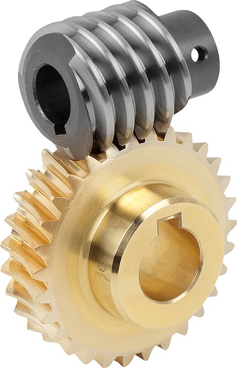
Can you explain the concept of worm and worm wheel in a worm gear?
In a worm gear system, the worm and worm wheel are the two primary components that work together to transmit motion and power. Here’s an explanation of the concept:
Worm:
The worm is a cylindrical shaft with a helical thread wrapped around it. It resembles a screw with a spiral groove. The helical thread is called the worm’s thread or worm thread. The worm is the driving component in the worm gear system.
When the worm rotates, the helical thread engages with the teeth of the worm wheel, causing the worm wheel to rotate. The angle of the helical thread creates a wedging action against the teeth of the worm wheel, resulting in a high gear reduction ratio.
One important characteristic of the worm is its self-locking nature. Due to the angle of the helical thread, the worm can drive the worm wheel, but the reverse is not true. The self-locking feature prevents the worm wheel from backdriving the worm, providing a mechanical brake or holding position in the system.
The worm can be made from various materials such as steel, bronze, or even plastics, depending on the application requirements. It is often mounted on a shaft and supported by bearings for smooth rotation.
Worm Wheel:
The worm wheel, also known as the worm gear, is the driven component in the worm gear system. It is a gear with teeth that mesh with the helical thread of the worm. The teeth on the worm wheel are typically helical and cut to match the angle and pitch of the worm’s thread.
As the worm rotates, its helical thread engages with the teeth of the worm wheel, causing the worm wheel to rotate. The rotation of the worm wheel is in the same direction as the worm’s rotation, but the speed is significantly reduced due to the high gear reduction ratio of the worm gear system.
The worm wheel is usually larger in diameter compared to the worm, allowing for a higher gear reduction ratio. It can be made from materials such as steel, bronze, or cast iron, depending on the application’s torque and durability requirements.
Together, the worm and worm wheel form a compact and efficient gear system that provides high gear reduction and self-locking capabilities. They are commonly used in various applications where precise motion control, high torque, and compactness are required, such as elevators, steering systems, and machine tools.


editor by CX 2023-11-17